Create a 3D scene for a new building project
In the city center of Frankfurt am Main, Germany, a new high-rise building is planned near the main train station, in a neighborhood being currently redeveloped. The architects would like to document their progress in the planning process and share updates with the stakeholders. Most particularly, they would like the stakeholders to give their feedback on the height and overall dimensions of the planned building. Your first step toward this goal will be to create a 3D scene in ArcGIS Pro.
Download the data and create a scene
First, you'll download the compressed zip file that contains some of the data needed for this tutorial.
- Download the tutorial data.
Note:
Depending on your web browser, you may be prompted to choose a file location before you begin the download. Most browsers download to your computer's Downloads folder by default.
- Locate the downloaded Frankfurt_Construction_Planning.zip compressed folder on your computer, and move it to a location of your choice, such as the Documents folder. Right-click it to extract its content.
- Open the extracted Frankfurt_Construction_Planning folder.
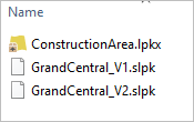
It contains three data files that you will use later in the tutorial: a layer package, ConstructionArea.lpkx, and two scene layer packages, GrandCentral_V1.slpk and GrandCentral_V2.slpk.
Next, you'll create a global scene in ArcGIS Pro.
- Start ArcGIS Pro. If prompted, sign in using your licensed ArcGIS organizational account.
Note:
If you don't have access to ArcGIS Pro or an ArcGIS organizational account, see options for software access.
- Under New Project, choose Global Scene.
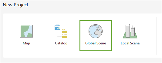
- In the New Project window, choose the following parameter values:
- For Name, type Frankfurt_Central_Station.
- For Location, click Browse and browse to your extracted data folder, Frankfurt_Construction_Planning and select it. Click OK.
- Uncheck the Create a new folder for this project check box.
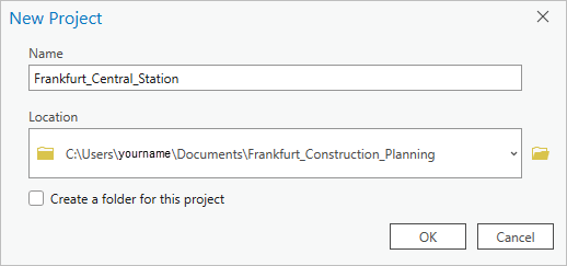
The new ArcGIS Pro project will be created in the same folder where your data is.
- Click OK.
A global scene is created.
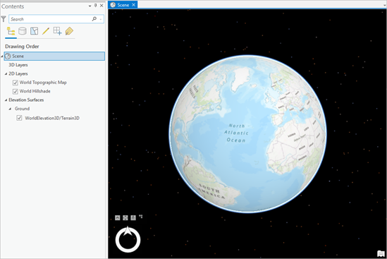
Note:
A global scene enables the display of 3D data for any extent up to the entire surface of the earth. It includes worldwide basemap and base elevation layers, and users can zoom out freely without the restriction of a local scene's extent.
- In the Contents pane, click Scene to select it. Click it again to make the name editable. Change the name of the scene to Frankfurt Central Station and press Enter.
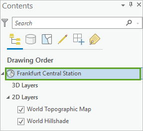
- In the Quick Access Toolbar, click Save.

You created a global scene, but it is currently empty. In the next section, you'll start adding data to it.
Add an integrated mesh layer
In the last section, you created an empty global scene. Next, you'll add a 3D integrated mesh layer that represents the entire city of Frankfurt, Germany. That data layer is hosted on ArcGIS Online.
- On the ribbon, click the View tab. In the Windows group, click the Reset Panes button and choose Reset panes for mapping (Default) .
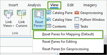
The Catalog pane appears. Resetting the panes allows you to quickly close panes that you won't be using and only show the Catalog pane, or others, depending on the option you choose.
- In the Catalog pane, click the Portal tab and click ArcGIS Online. In the Search field, type Frankfurt Integrated Mesh owner:Scene_Layers
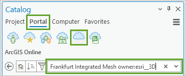
- In the list of results, right-click the Frankfurt Integrated Mesh scene layer, and choose Add To Current Map.
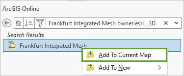
The layer is added to the scene, and the scene automatically zooms in to the extent of that layer.
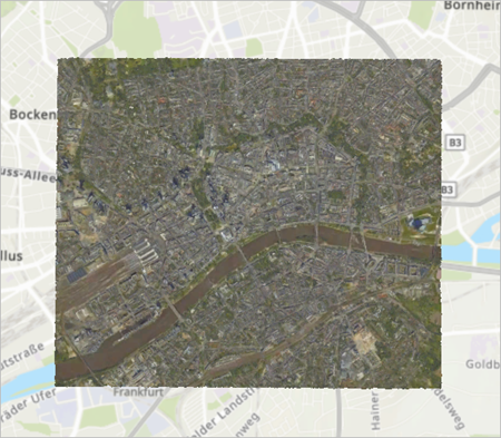
You'll now change the basemap so that the integrated mesh layer blends better with the entire scene.
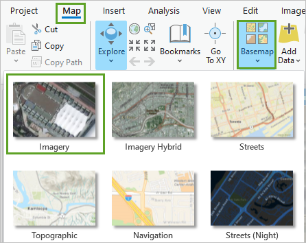
- On the ribbon, click the Map tab. In the Layer group, click Basemap. Choose the Imagery basemap.
Note:
If the Imagery basemap was already selected by default, you don't need to change anything. If your organization offers a customized list of basemaps, you can choose one of your liking.
The basemap updates. You'll now explore the integrated mesh layer in the 3D view.
- In the scene, above the Navigator wheel, click Show full control.
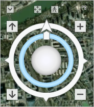
The Navigator wheel expands to include 3D navigation functionality.
- Use the middle Navigator wheel to tilt and rotate the scene. You can also use the mouse wheel button to zoom in and out and drag to pan.
Note:
To learn more about the options for 3D navigation, see Navigation in 3D.
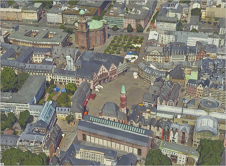
- Ensure that the scene is tilted to see the data in a 3D perspective. Zoom closer to the mesh layer and pan to explore different areas of the city.
Note:
What is integrated mesh data? It is typically captured by an automated process meant to construct a real-world 3D representation out of large sets of overlapping imagery. The result integrates the original input image information as a textured mesh including 3D objects, such as buildings and trees, and elevation information.
For example, a project site could be captured daily by a drone flight, and the resulting data can be visualized as an integrated mesh. You can use ArcGIS Drone2Map to create this type of data. Learn more about Drone2Map in the tutorial Create 3D products with ArcGIS Drone2Map.
Integrated mesh scene layers can also be created for citywide 3D mapping, such as in the example of the city of Frankfurt am Main in this tutorial. To visualize this data in a well-performing way, the integrated mesh scene layer has different levels of detail (LODs). When you zoom out and increase the distance to your scene, the complexity of the 3D data is decreased as well.
- Press Ctrl+S to save the project.
Your scene now contains an integrated mesh layer displaying the city of Frankfurt in great detail. In the next section, you'll add a layer representing the construction area for the new building.
Add the 2D construction area
You'll now add the construction area layer to your scene. A simple 2D polygon represents the area where the construction will take place. It is stored in a layer package and is part of the data you downloaded at the beginning of the tutorial.
- In the Catalog pane, click the Project tab. Expand Folders and expand Frankfurt_Construction_Planning.
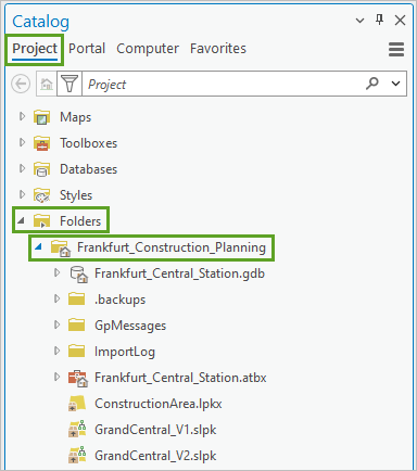
- Right-click ConstructionArea.lpkx and choose Add To Current Map.
The ConstructionArea layer is added to the Contents pane under the 2D Layers category.
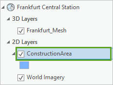
- In the Contents pane, right-click the ConstructionArea layer, and choose Zoom To Layer to zoom in to the layer.

- In the scene, zoom and pan to examine the ConstructionArea polygon.
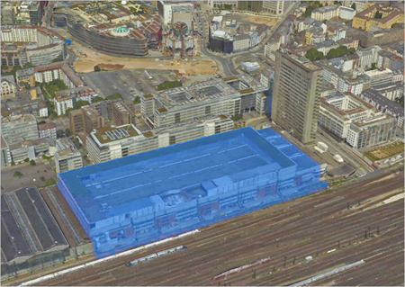
Because it is a 2D polygon added to a 3D scene, it is displayed draped on the Frankfurt_Mesh layer. In this case, it is displayed draped over an old building that will be demolished to make way for the new construction.
Note:
When an integrated mesh layer is added to a scene, it supersedes the ground and basemap of that scene in the display. Any other layers that have an elevation property set to On the ground draw on the ground as well as on the integrated mesh, which is why you are seeing the ConstructionArea polygon with this draped effect.
You want to ensure that features such as the ConstructionArea polygon can be clicked and selected in the scene, without the mesh layer being affected and displaying a flashing effect. To optimize the user experience, you'll fine-tune the selection settings.
- In the Contents pane, click the List By Selection tab. Uncheck the Frankfurt_Mesh layer.
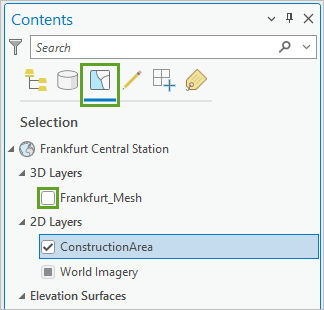
Note:
The Selection tab allows you to specify which layers are selectable and which ones are not.
Unchecking the mesh layer means it cannot be selected.
- Click the List By Drawing Order tab to return to the Contents pane default display.

- On the ribbon, click the Map tab. In the Navigate group, click the Explore drop-down arrow. In the drop-down list, choose Selectable Layers.
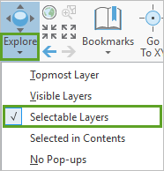
You'll now examine the content of the informational pop-up.
- In the scene, click the ConstructionArea polygon to display the pop-up.
- Review the content of the pop-up. Under ProjectWebSite, click the web link to learn more about the construction project.
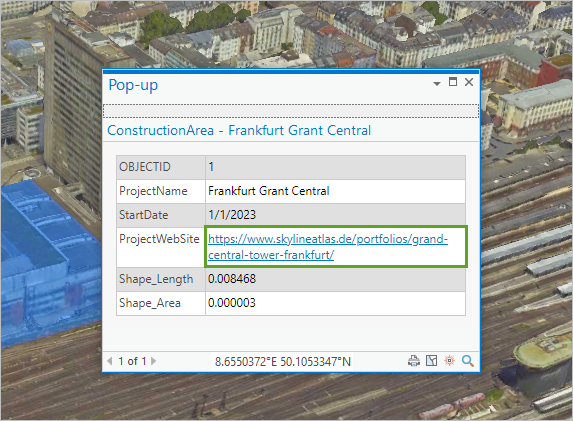
The web page (in German) appears in a web browser window.
- When you are done reviewing the web page information, come back to ArcGIS Pro and close the pop-up.
- Press Ctrl+S to save the project.
Your scene now contains the integrated mesh layer displaying the city of Frankfurt in great detail and a polygon feature representing the construction area for the new building. Next, you'll add the 3D representation of the planned building.
Add the 3D building layer
You'll now add the 3D representation of the planned building, and customize its display.
- In the Catalog pane, under the Project tab, if necessary, expand Folders and expand Frankfurt_Construction_Planning.
- Right-click GrandCentral_V1.slpk and choose Add To Current Map.
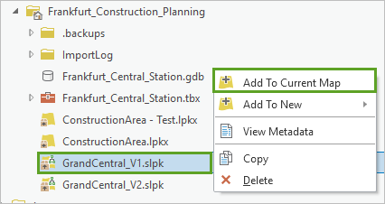
The GrandCentral_V1 scene layer is added to the scene and to the Contents pane under the 3D Layers category. It contains the first version for the new planned building, represented as a 3D object stored in a building scene layer package. It was created from a BIM-design Revit file using the ArcGIS Pro Create building scene layer tool.
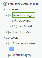
Note:
Building information modeling (BIM) is the process of creating and managing 3D, 4D, and 5D information for a construction project across multiple disciplines. ArcGIS Pro supports BIM-design files from Autodesk Revit as a BIM file workspace.
Building scene layers allow you to store, distribute, and analyze detailed information from construction documentation in ArcGIS. In the BIM, designers, builders, and owners generate many kinds of information about buildings throughout the life span of the building. You can use the building scene layer to capture the geometry, semantic organization, and attributes in 3D construction data for use with other GIS content.
- Zoom and pan to examine the GrandCentral_V1 building.
- Tilt the view so you can see the tower in the draft better.
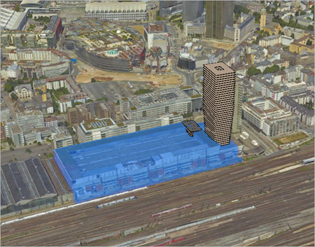
Note that the base of the building is not visible because it clashes with the old building captured in the integrated mesh layer. You will fix this issue later in the tutorial.
- In the Contents pane, uncheck the Frankfurt_Mesh layer to turn it off and view the entire planned building.
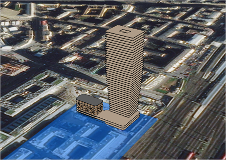
The building now displays on top of the ConstructionArea polygon, the Imagery basemap and the Terrain layer, which does not show any of the 3D structures of the city. You can now clearly see the main building's base, as well as a smaller building on the side.
Note:
The construction area appears much larger than the building itself. This is because this is a multiphase project, and the first version of the design only shows the first set of buildings that will be built on this site.
- In the Contents pane, review the GrandCentral_V1 layer.
The layer has two view options: Overview and Full Model. The Overview represents mostly the external shell of the building. The Full Model contains more details and is organized in several disciplines, such as architectural, mechanical, and structural.
- Select the GrandCentral_V1 layer and turn the Full Model on. Expand Full Model and expand Architectural. Check the box next to Architectural to display all the architectural sub-layers.
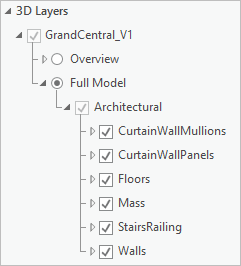
The tall building includes only the Floors and Mass elements. The smaller building contains more elements such as Walls and StairsRailing.
- Turn the Floors and Mass layers on and off to see how the tall building changes.
- Zoom in and rotate the scene to see the details of the smaller building.
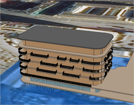
- In the Contents pane, turn the various architectural layers on and off to see the role that each one plays.
- Zoom back out to see the entire building set.
To see the building in the context of the 3D mesh, you'll turn that layer back on.
- In the Contents pane, turn the Frankfurt_Mesh layer back on.
- In the Contents pane, turn on the Floors layer and turn off the Mass layer.
The individual floors can be difficult to distinguish. You'll choose a different lighting option to improve the rendition of the Floors layer.
Note:
By default, the built-in geometry properties of a 3D object are used to shade it for the scene's current light position. The properties used for lighting are 3D vectors—or normals—that define the direction that each face will reflect light. The shading of each face of the 3D object is calculated from its normal. You can adjust the lighting option for a layer.
- In the Contents pane, click the Floors layer to select it.
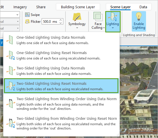
- On the ribbon, click the Scene Layer tab. In the Faces group, click Lighting. In the Lighting drop-down list, choose Two-Sided Lighting Using Reset Normals to improve the rendition of the Floors layer.
- In the Contents pane, turn the Mass layer back on.
- Switch back to the Overview option, and make sure the Overview layer is selected.
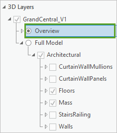
- Apply the same Two-Sided Lighting Using Reset Normals lighting option to the Overview layer.
- Collapse the GrandCentral_V1 layer.
- Press Ctrl+S to save the project.
You have now created a 3D scene that brings together an integrated mesh layer representing the city of Frankfurt in great detail, a polygon feature layer representing the overall construction area, and a 3D object representing the planned building. Next, you will modify the integrated mesh layer to better align it with the new building.
Modify the area surrounding the new building
The Frankfurt_Mesh layer shows the old building that currently exists on the construction site. As a result, it hides the lower part of the new building. You will modify the mesh layer, flattening it to make space for the new building. This change will happen within the scene only, and will not affect the original mesh data.
Note:
An integrated mesh scene layer can be modified in different manners depending on the use case. First, you can combine the mesh layer with planned construction such as in this tutorial, flattening the existing buildings to make room for the new ones. You could show the mesh along with the local underground infrastructure, cutting holes into the mesh to visualize the pipes or other assets. Another option would be to choose to focus on a limited area of the mesh layer by masking out all other areas.
In all cases, you'll perform an integrated mesh modification, which is scene-specific and does not affect the original data. The modification's parameters are stored in the project's geodatabase. This makes it possible to create many different scenes without having to duplicate the mesh data.
Add modification to the integrated mesh layer
In this section, you'll create an integrated mesh modification based on the ConstructionArea layer, using the Replace option to flatten the area.
Note:
The modification will replace the mesh geometry with the geometry of the ConstructionArea polygon, creating a flat plateau for that area at the minimum z-value (height) on the ground.
- In the Contents pane, right-click the ConstructionArea layer, and choose Zoom to Layer.

The view in the scene updates to display the construction area.
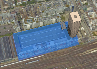
It will be easier to view the modification of the mesh layer if the ConstructionArea layer is turned off.
- In the Contents pane, turn off the ConstructionArea layer.
You'll now create the modification.
- In the Contents pane, select the Frankfurt_Mesh layer.
- On the ribbon, click the Data. In the Modification group, click Add.
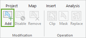
- In the Add Modification window, choose Import from existing polygon feature layer.
- In the drop-down list, choose ConstructionArea. For Mode, verify that Replace is selected.
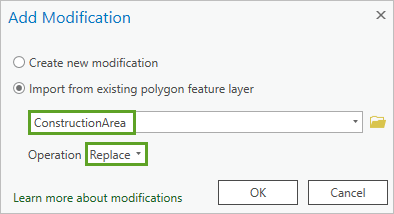
- Click OK.
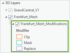
In the Contents pane, under Frankfurt_Mesh, the new modification appears.
Note:
The three options enable the different types of modifications. Clip allows you to cut out the integrated mesh to make the layers underneath visible. Mask allows you to hide the mesh beyond an area of interest. It can also be used to straighten the edges of the integrated mesh. Replace changes parts of an integrated mesh based on a polygon to flatten the area.
- In the scene, zoom, pan, and rotate to inspect the modification.
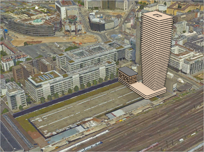
The portion of the mesh corresponding to the ConstructionArea polygon is flattened. It does not obstruct the view of the new planned building any longer.
- Press Ctrl+S to save the project.
Edit the modification polygon
In the previous section, you added the modification polygon to the integrated mesh layer. The construction area does not extend to the end of the block on the east side of the building. You are asked to rectify this issue so that the end of the block is flattened too. You will edit the modification polygon using the editing tools to extend it eastward.
- In the scene, review the flattened area and the remaining bulging slice.
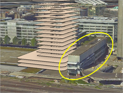
This is the mesh area you want to include in the modification.
- In the Contents pane, right-click the Frankfurt_Mesh _Modifications layer and select Zoom To Layer to fully see the modification area.
You will also turn off the building to better see the entire modification polygon.
- In the Contents pane, uncheck the box for the GrandCentral_V1 layer to turn it off.
Next, you'll select the modification polygon.
- In the Contents pane, right-click the Frankfurt_Mesh_Modifications layer, and choose Attribute Table.
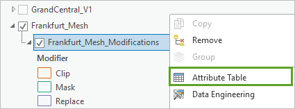
- In the attribute table, review the only row present.

This is the modification polygon that you just created. You can see in the Shape attribute that the feature is of the Polygon Z type. This means it has z-values and is a 3D polygon, not just a 2D one. The minimum z-value of the polygon is defining the height of the replacement in the integrated mesh layer. Some of the other attributes, such as ProjectName, StartDate, and ProjectWebSite, are inherited from the mesh layer. Finally, the Modifier attribute indicates the type of modification used, in this case, Replace.
- Click in the first column of the row to select the feature.

In the scene, the selected polygon's outline is highlighted in cyan blue.
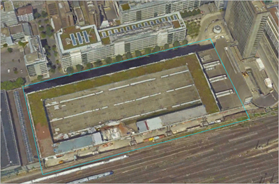
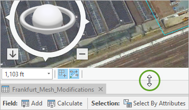
- If necessary, adjust the size of the attribute table pane to better see the scene.
- On the ribbon, click the Edit tab. In the Tools group, select Edit Vertices.

In the scene, the vertices of the polygon appear as green squares.
- Click the vertex in the lower right corner to select it, and move it just beyond the unwanted mesh slice.
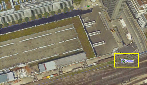
- Similarly, move the upper right vertex to build an extended rectangular shape.
- On the edit vertices toolbar, click the Finish button to complete your sketch. Alternatively, you can press F2.
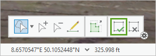
The polygon updates and the flattened area extends, eliminating the unwanted slice.
- Zoom and pan to review the extended polygon and the extended flattened area.
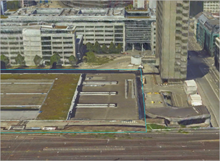
Note:
You can repeat the edits until you have achieved the correct modification.
- On the ribbon, on the Edit tab, in the Manage Edits group, click Save.
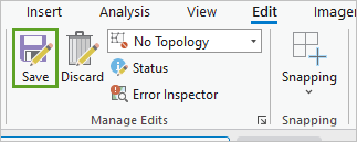
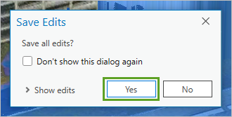
- In the Save Edits window, click Yes to save all your edits.
- On the ribbon, on the Edit tab, in the Selection group, click Clear to remove the selection.

- Close the Modify Features pane.

- Close the attribute table.
- In the Contents pane, turn off the Frankfurt_Mesh_Modifications layer.
The modification will still be applied, but the polygon itself will not be visible.
- Press Ctrl+S to save the project.
Your 3D scene is now fine-tuned and almost ready to be shared with stakeholders. In the next section, you'll add bookmarks.
Add bookmarks
In the last steps, you prepared all the layers to align well. Before sharing with your audience, you will add bookmarks to make it easier to navigate the scene and find the best angles to visualize the progressing construction. First, you'll create a bookmark showing an overview of the city of Frankfurt.
- In the Contents pane, select the Frankfurt_Mesh layer, right-click and choose Zoom To Layer.
The scene zooms out to see the entire city of Frankfurt.
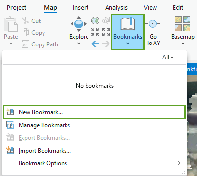
- On the ribbon, click the Map tab. In the Navigate group, click Bookmarks. In the drop-down list, choose New Bookmark.
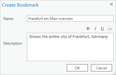
- In the Create Bookmark window, for Name, type Frankfurt am Main overview. For Description, type Shows the entire city of Frankfurt, Germany.
Next, you'll create a bookmark to show the construction area overview.
- Click OK to create the bookmark.
- In the Contents pane, turn the GrandCentral_V1 layer on.
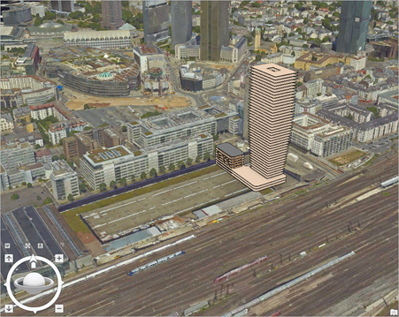
- In the Contents pane, right-click the ConstructionArea layer and choose Zoom To Layer. This gives you a good overview of the construction area. Tilt the view to optimize the angle.
- On the ribbon, on the Map tab, click Bookmarks. In the drop-down list, choose New Bookmark.
- In the Create Bookmark window, for Name, type Central station construction area. For Description, type Overview of the construction area next to the central train station.
- Click OK to create the bookmark.
- On the ribbon, click Bookmarks again.
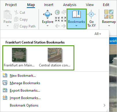
You can see the two bookmarks you created.
- Click both bookmarks to see how they allow you to quickly navigate the scene.
- When you are done testing the bookmarks, click the Central station construction area bookmark, as you want to save the project with that view.
- Press Ctrl+S to save the project.
You have created an integrated mesh modification and edited the modification polygon to optimize the visualization of the proposed building design within the 3D scene. You then created bookmarks to improve the navigation. Your scene is now ready to be published online.
Share the 3D scene and upload a new building design
You'll now share your scene to ArcGIS Online to share with the project stakeholders. Then, you'll learn how to update the building layer to show the new design versions delivered by the architects, as the project progresses.
Publish the 3D scene
In this section, you'll publish the scene from ArcGIS Pro to ArcGIS Online to create a web scene. First, you'll rename the building layer to a more informative name.
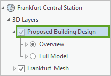
- In the Contents pane, click GrandCentral_V1 to select it. Click it again to rename it, type Proposed Building Design, and press Enter.
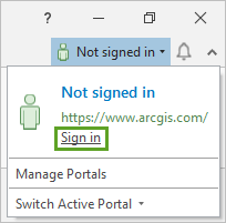
- In ArcGIS Pro, at the upper right of the ribbon, look for your Sign-in Status. If it says Not signed in, click Sign in and enter your ArcGIS credentials.
- On the ribbon, click the Share tab. In the Share As group, choose Web Scene.
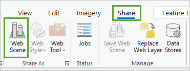
The Share As Web Scene pane appears.
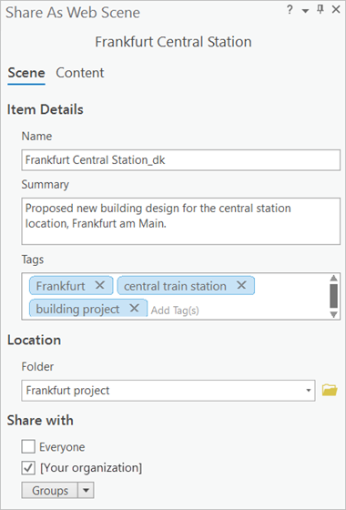
- In the Share As Web Scene pane, on the Scene tab, input the following:
- For Name, type Frankfurt Central Station followed by your initials (for instance, Frankfurt Central Station YN).
- For the Summary, type Proposed new building design for the central station location, Frankfurt am Main.
- For Tags, type Frankfurt, central train station, building project. Press the Tab or Enter key after each word.
- For Location, choose a folder of your choice in your ArcGIS account. Optionally, you can create a folder.
- For Sharing Level, choose organization to make the web scene available to everyone within your organization.
Note:
Listing tags will allow you and your audience to search for the new web scene easily in your ArcGIS Online organization. Adding your initials to the web layer name ensures that it remains unique, even if someone else in your ArcGIS Online organization does this same tutorial.
- In the Share As Web Scene pane, under Finish Sharing, click Analyze.

An error appears: 00374 Unique numeric IDs are not assigned.
- Right-click the error and click Open Map Properties To Allow Assignment.
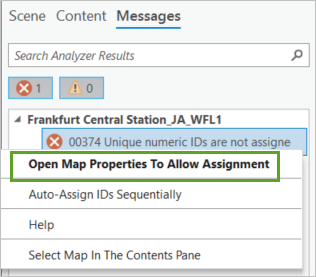
The Map Properties: Frankfurt Central Station window appears for the global scene.
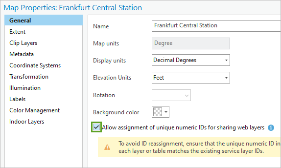
- In the Map Properties: Frankfurt Central Station window, click the General tab. Check the box for Allow assignment of unique numeric IDs for sharing web layers and click OK.
- In the Share As Web Scene pane, click Analyze again.
The tool should report that no errors or warnings were found. If more issues are found, you should resolve them before sharing the scene online.
- When ready, under Finish Sharing, click Share.

The process runs for some time. A status bar at the bottom of the pane shows progress, but you can also monitor the process in more detail.
- Under Finish Sharing, click Jobs.

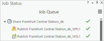
The Job Status pane appears, and you can see the publishing status for the various scene elements. When the process is complete, a green check mark appears next to the web scene name.
- Close the Job Status pane.
You'll now open the web scene in ArcGIS Online.
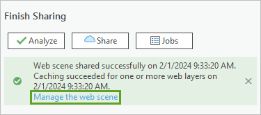
- In the Share As Web Scene pane, click the Manage the web scene link.
- If prompted, enter your ArcGIS Online credentials.
The web scene item page opens in ArcGIS Online.
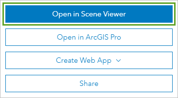
- On the web scene item page, click Open in Scene Viewer.
The web scene appears in your web browser.
- In the scene, drag to pan.
- Click the Toggle to pan or rotate in 3D button to switch to the rotate mode.
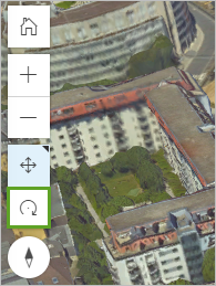
- Drag to rotate the scene and observe the building design and how it fits in the surrounding urban environment.
- If necessary, move the pointer anywhere in the scene to reveal the two bookmarks at the bottom of the browser.
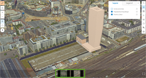
- Click the first bookmark. Then click the second bookmark.
Each time, the scene updates to the bookmarked view.
The web scene you published is easy to navigate and makes it easy for stakeholders to view the planned building design in the context of the larger urban environment.
Update the building design
The GrandCentral_V1 building design was just the first version of the project, and the architects will produce new versions on a regular basis during the entire design phase. Each time a new version comes in, you can upload it directly to the web scene to replace the previous design efficiently. You'll do that with the second building design, GrandCentral_V2. First, you'll upload the scene layer package containing that second building version to ArcGIS Online.
- On the ArcGIS Online web scene, click Options to expand the drop-down list and choose Content. If necessary, click Leave.
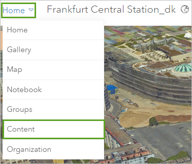
The Content page appears, listing all the content in your account.
- Under Folders, choose the folder location where your scene was published.
The files for the web scene and all its components are listed within that folder.
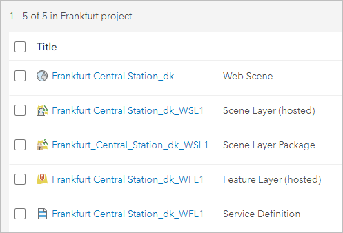
Note:
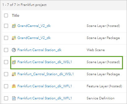
Because you published an entire web scene, all the layers it contains are named after that web scene and did not keep their original names. For instance, the first version of the building layer is now named Frankfurt Central Station_<Your Initials>_WSL1, instead of the original GrandCentral_V1.
- On the Content page, click New item.
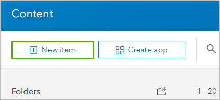
- In the New item window, click Your device and browse to the Frankfurt_Construction_Planning folder location on your local machine.
- Select the GrandCentral_V2.slpk scene layer package, and click Open.
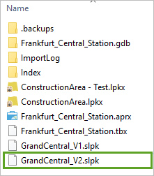
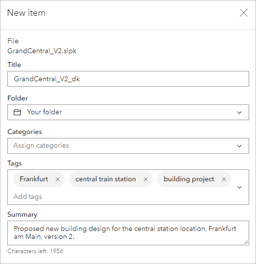
- For How would you like to add this file?, choose Add GrandCentral_V2.slpk and create a hosted scene layer. Click Next.
- For Title, add your initials to the suggested default.
- For Tags, type Frankfurt, central train station, and building project. Press Enter between each tag.
- For Summary, type Proposed new building design for the central station location, Frankfurt am Main, version 2.
- Click Save.
The scene layer package is uploaded to your ArcGIS Online account. You'll now share this item with your organization and use it to update the building design.
- On the GrandCentral_V2 <your initials> item page, click Share.

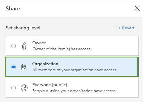
- In the Share window, select Organization and click Save.
- On the ribbon, click Content to go back to your scene folder.

The scene layer containing the first version of the building is currently named Frankfurt Central Station_<Your Initials>_WSL1.
- Click the Frankfurt Central Station_<Your Initials>_WSL1 scene layer to open the item page.
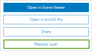
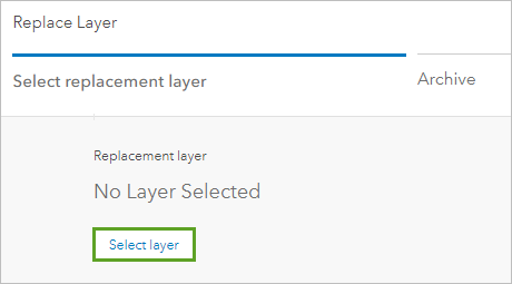
- On the scene layer item page, click the Replace Layer button.
On the Replace Layer page, the first of three steps is Select replacement layer.
- For Replacement layer, click Select layer.
- In the Select replacement layer window, in the list of layers, locate GrandCentral_V2, and click Select.
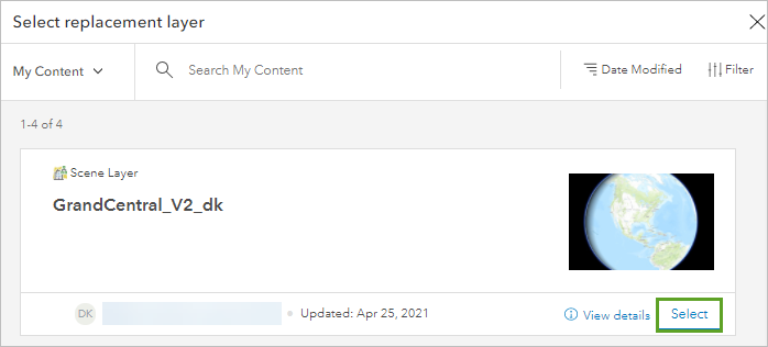
When the replacement layer is validated, you'll see a green check mark and the message This replacement is compatible with the current layer.
- In the lower right corner, click Next.
The second step is Archive. The layer that is about to be replaced will first be archived. This way if there is an issue with the replacement, it can be undone.
- Turn on the Replace item information option.

With the option, when the layer is replaced, the item information from the GrandCentral_V2 layer will be used (for instance, its title, description, and tags). If you kept the option off, the item information of the older building layer would be used.
- Click Next.
The last step of the Replace layer process is Summary, which lists all the replacement information.
- Click the Replace button to complete the replacement process.
- On the top toolbar, click Content. In the content list, click the Frankfurt Central Station_<your initials> web scene.
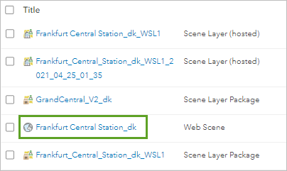
- On the web scene item page, click Open in Scene Viewer to open the web scene.
- If necessary, go to the bookmark Central Station Construction Area.
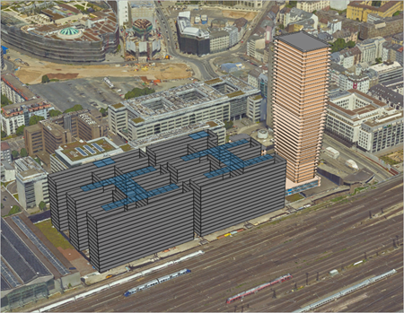
The second version of the building design appears. You can see that it has much expanded compared to the first version.
In this tutorial, you created a 3D scene showing a new construction project planned in Frankfurt, Germany. You included an integrated mesh scene layer to display the urban context of the project. You then added the construction area polygon, and a 3D representation of the planned building derived from a BIM-design file. You added a modification to the integrated mesh layer to flatten it within the construction area, and extended the modification polygon. You then shared the scene with the project's stakeholders in ArcGIS Online. Finally, you replaced the first version of the building with a second version, making the swap directly in ArcGIS Online.
You can find more tutorials in the tutorial gallery.

