Refine irregular surfaces with correction polygons
Download the project
To use the ArcGIS Reality Studio project built for you, you'll download it and extract it to a specific location.
- Download the Reality_TrainingData02.zip file and locate the downloaded file on your computer.
Note:
This file has a size of 4.5 GB, so it may take several minutes to download. Most web browsers download files to your computer's Downloads folder by default.
- Extract the zipped data to your C:\ drive.
Note:
Most extraction programs enable you to choose the output location of the extracted file. Ensure your output location is C:\ before running the program.
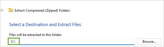
The folder is extracted. Its path is C:\Reality_TrainingData02.
Caution:
The path for the data should be exactly C:\Reality_TrainingData02.
Open the project
You'll open a project to repair these two types of reconstruction artifacts.
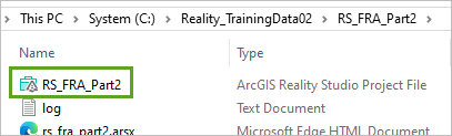
- Open the extracted Reality_TrainingData02 folder and open the RS_FRA_Part2 folder, then double-click the RS_FRA_Part2 project file.
- If you are prompted to stop contributing to the previous project, click OK.
The project opens. The Globe view shows a region of interest with a small, two-block area.
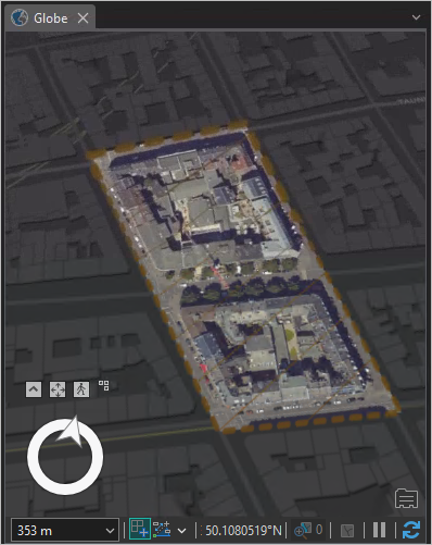
- Zoom to the small area on the south edge of the northern block.

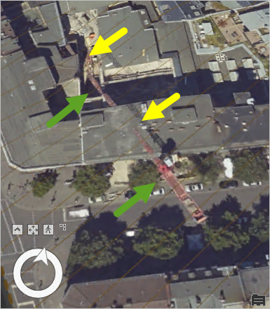
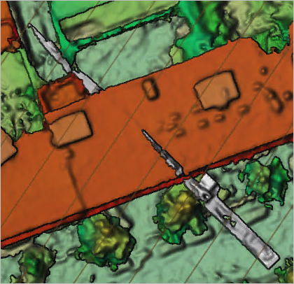
In this area, a construction crane has been in use. It is likely that it moved between times that it was captured by different flight lines. As a result, the True Ortho layer shows it with gaps. In the following image, green arrows indicate the crane where it was correctly captured, and yellow arrows indicate gaps.
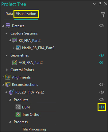
- In the Project Tree pane, under Reconstructions, expand REC2D_FRA_Part2 and expand Products. Use the Toggle Visibility button to turn the True Ortho layer off and turn the DSM layer on.
Tip:
To turn a layer on, point at the layer to reveal the Toggle Visibility button. Click Toggle Visibility.
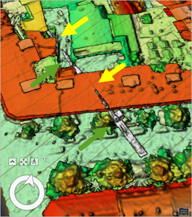
The DSM layer also shows breaks in the crane. You'll use a correction geometry to repair the breaks in the crane.
Create a correction geometry
In ArcGIS Reality Studio, you can use correction geometries to replace elevation values in the reconstruction outputs. You'll create a correction geometry layer for the project.
- On the ribbon, click the Home tab. In the Input group, click Geometries and choose Create Geometry.

The Create tool opens.
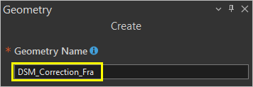
- For Geometry Name, type DSM_Correction_Fra.
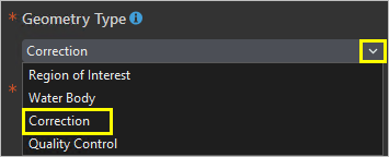
- For Geometry Type, choose Correction.
- For Spatial Reference, choose RS_FRA_Part2.
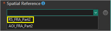
The spatial reference of the geometry now matches the spatial reference of the RS_FRA_Part2 capture session, ETRS 1989 UTM Zone 32N / VCS: DHHN2016 height. Choosing a matching spatial reference saves clicks and avoids potential mistakes in browsing to and selecting a spatial reference.
- Click Create.
The new correction geometry layer is added to the Project Tree pane.
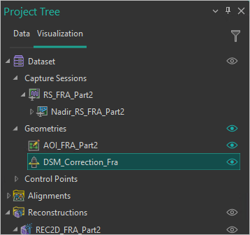
- Click DSM_Correction_Fra to select the layer.
While the layer is selected, the Edit tab becomes visible on the ribbon.
Add a correction polygon for the crane
Next, you'll digitize a correction polygon around the crane and assign it an elevation.
- On the ribbon, click the Globe tab. Click Nadir View.
- On the ribbon, click Drawing Mode and choose Parallel Drawing Mode.
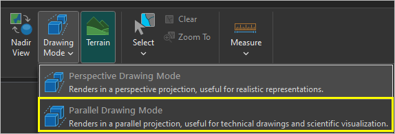
- Zoom in to the crane area.
- Ensure that the DSM_Correction_Fra layer is selected in the Project Tree pane.
- On the ribbon, click the Edit tab.
- In the Elevation group, for Elevation Source, choose DSM_REC_2D_FRA_Part2.

- In the Elevation group, click Mode and choose Constant.
- Move the pointer over a gray area near the southern end of the crane.

The elevation value, taken from the DSM layer, is displayed at the bottom of the Globe pane. The crane's elevation is approximately 133 meters (or 437 feet).
- On the ribbon, in the Elevation group, type 437 ft.
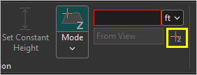
When you set the constant z-height, a semitransparent layer appears, muting the colors of areas below that elevation.
- On the ribbon, in the Features group, click Create Polygon.
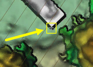
- Click the southwest corner of the crane.
Tip:
While creating your polygon, to temporarily enable pan mode, press and hold C while. To temporarily disable Snapping, press and hold the spacebar.
- Click the northwest corner of the crane.
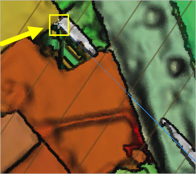
After you've added the northwest corner, when you move the pointer, construction guide lines with snapping for perpendicular and parallel lines appear.
- Click the northeast corner of the crane.
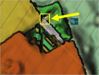
- Double-click the southeast corner of the crane.
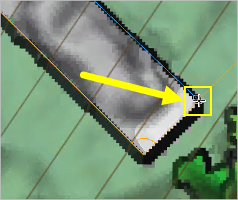
The crane correction polygon feature is completed.
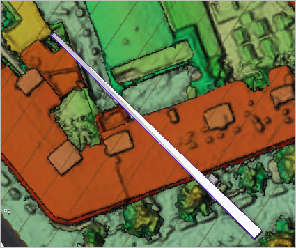
- Click the Finish button.

- Tilt and rotate the view until you can see the flat crane correction polygon over the irregular DSM surface.
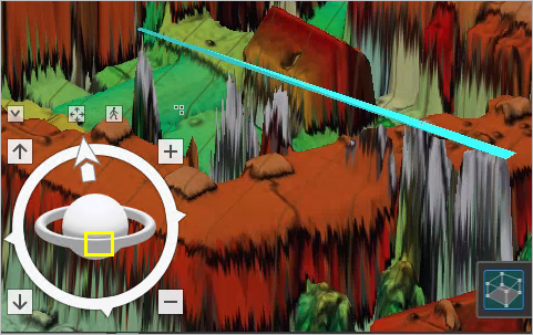
- On the ribbon, on the Edit tab, in the Manage Edits group, click Save. Click Yes.
You've created a correction polygon to set the elevation for the crane. Next, you'll straighten a building edge with another correction polygon.
Correct the edge of a courtyard
In the southern block in the project's region of interest, there is a building with a courtyard. The edges of this courtyard, and the surrounding buildings, are not linear. You'll add another correction polygon to clean up these edges and set the elevation of the courtyard.
- On the Globe tab, click Nadir View.
- In the Project Tree pane, in the Products section, turn off the DSM layer and turn on the True Ortho layer.
- Zoom to the southern part of the southern block in the region of interest.

The courtyard area is rectangular, but edges of the buildings and surrounding walls are not straight.
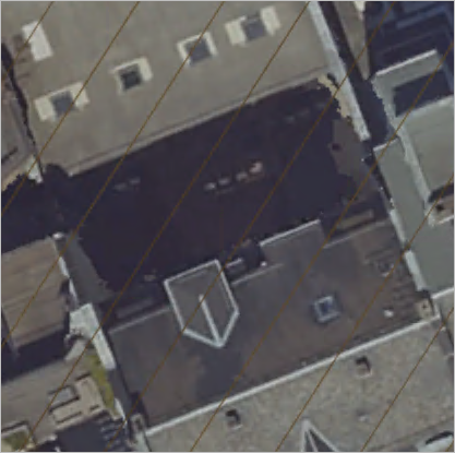
- In the Project Tree pane, select the DSM_Correction_Fra layer.
- On the ribbon, click the Edit tab. In the Features group, click Create Polygon.
- Click the southwest corner of the courtyard.
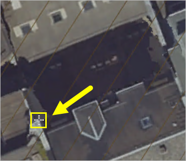
- Click the northwest corner of the courtyard.
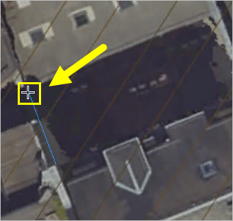
- Click the northeast corner of the courtyard.
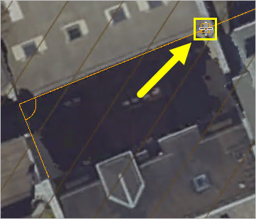
- Double-click the southeast corner of the courtyard.
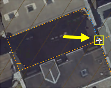
- Click Finish.
- In the Project Tree pane, turn the True Ortho layer off and turn the DSM layer on.
- Tilt the view slightly.
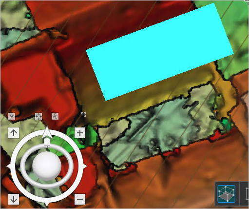
The courtyard polygon is floating at the crane height, far above the courtyard surface.
Set the elevation of the courtyard correction polygon
You'll set the elevation of the polygon interactively.
- In the Project Tree pane, select the DSM_Correction_Fra layer.
- On the ribbon, on the Edit tab, in the Elevation group, change the Elevation Source to DSM REC2D_FRA_Part2.
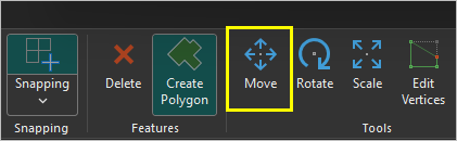
- In the Tools group, click Move.
An XYZ axis selector appears above the middle of the selected polygon.
- Move the pointer over the green z-axis arrow.
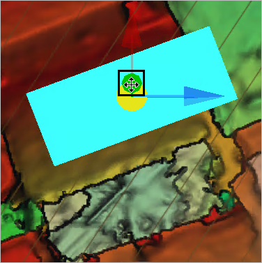
- Click the z-axis arrow and drag the courtyard polygon down until the height displayed on the bottom of the Globe pane is about 97 meters, or when the polygon appears to dive into the DSM surface.
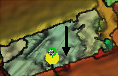
The bottom of the Globe pane shows the height.
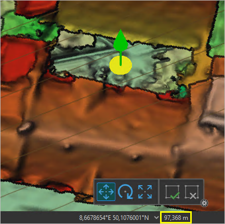
- Click Finish.
- On the Edit tab, click Save. Click Yes.
- On the Edit tab, click Mode.
The z-mode helper plane is turned off. Now that you've created correction polygons for the crane and the courtyard and set their elevations, you're ready to apply the corrections to the output products.
Apply the corrections
You'll update the settings for the reconstruction and reprocess the data to apply corrections based on the correction polygons.
- In the Project Tree pane, right-click REC_2DFRA_Part2 and choose Settings.
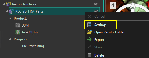
The Reconstruction pane appears.
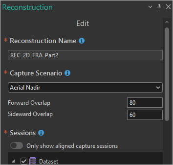
- Scroll down to the Advanced Settings section and expand it. For Correction Geometries, choose DSM_Correction_Fra.

The correction geometries that you created are added to the reconstruction.
- Click Save.
A warning appears that your changes will overwrite the current version of the data.
- Click OK.
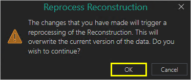
The reconstruction is reset and automatically submitted. The True Ortho and DSM layers are removed from the Globe pane.
- On the ribbon, click the Reconstruction tab. In the Workspace group, click Manage Workspace.

The workspace manager pane opens below the Globe view.
- In the workspace manager pane, click Start Contribution.

Once the contribution is started, a command-line interface window opens. It tracks the progress of the tasks submitted to the workspace.
The reprocessing takes about ten minutes on recommended hardware. Once the process finishes, you can examine the changes to the DSM and True Ortho layers.
- In the workspace manager, when the Status field is Finished, click Stop Contribution.

- On the Globe tab, click Nadir View.
- In the Project Tree pane, turn off the DSM_Correction_Fra layer.
- Turn on the DSM layer.
- Zoom to the crane location.
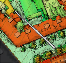
The DSM pixels for the crane are all set to the crane's elevation. The crane is drawn in light gray.
- Pan to the courtyard.
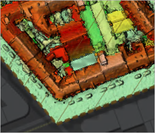
The pixels of the courtyard are green, the color of the street level elevation.
- Turn off the DSM layer.
- Turn on the True Ortho layer.
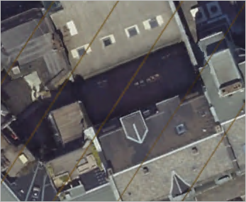
The building edges are straighter around the courtyard.
- Click Save Project.
In this tutorial, you created correction geometries to set the elevations of the crane and the courtyard. You applied these corrections to the reconstruction and checked the changes in the DSM and True Ortho output layers.
You can find more tutorials in the tutorial gallery.