Import and incorporate 3D models in a scene
Open a map package
To start, you will download the data needed for the tutorial, import a map package (.mpkx file) into ArcGIS Pro, and save a new project.
- Download the Importing-Content.zip compressed folder.
- Locate the downloaded file on your computer and unzip it to a location on your computer, for example, drive C.
- Open the Importing-Content folder.
This folder contains a map package (.mpkx file) and a data folder. A map package is a file that contains an ArcGIS Pro map or scene along with all of its data and settings.
- Double-click Import_Content.mpkx.
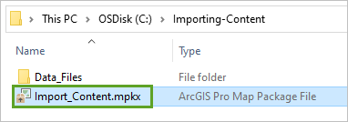
ArcGIS Pro opens to a new untitled project. If prompted, sign in with your ArcGIS account.
Note:
If you don't have access to ArcGIS Pro or an ArcGIS organizational account, see options for software access.
A local scene named Scene1 has been imported into the project from the .mpkx file. The scene includes a 3D visualization of several buildings in the Redlands Packing House District in California. The data was created by Esri.
- On the ribbon, click the View tab. In the Windows group, click Reset Panes and click Reset Panes for Mapping (Default).
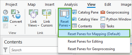
This ensures that the Contents and Catalog panes are open and that other panes are closed.
Before you continue, you'll save the new project in the same folder that contains the data files.
- On the Quick Access Toolbar, click the Save button.

- In the Save Project As window, browse to and select the Importing-Content folder, so Name is set to Importing-Content.
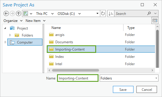
- Click Save.
Above the ribbon, the name of the map changes to Importing-Content.

Place and interact with a model on a 3D object feature layer
3D scenes can be enhanced and made more realistic with the addition of 3D symbols and real-world models. Some of these models can be quite detailed or unique to a specific area or subject. As a result, many third-party model formats are supported in ArcGIS Pro. In this section, you will create a new 3D object feature class and import a .glb file with a model of a train. You'll use the editing tools to size, position, and scale the train in the scene.
Note:
For more information about which formats are supported by 3D object feature layers, see the ArcGIS Pro help.
- In the Catalog pane, on the Project tab, expand Databases.
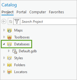
The Default geodatabase is listed.
- Right-click Default.gdb, click New, and click Feature class.
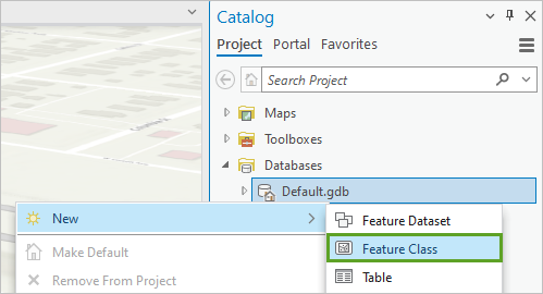
The Create Feature Class pane appears.
- In the Create Feature Class pane, set the following parameters:
- For Name, type passenger_train.
- For Alias, type Passenger Train.
- For Feature Class Type, choose 3D Object.
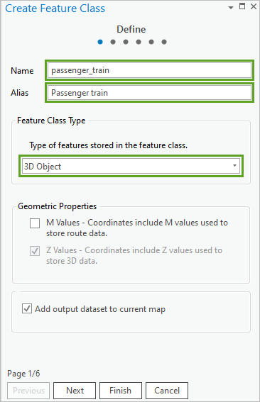
The 3D Object type is based on the multipatch framework with added features. You will use a 3D object feature layer for the passenger train because the model you will import contains features that are not supported by a simple multipatch layer. The train also uses advanced materials, such as reflection, emissivity, and ambient occlusion. The 3D object feature layer type is best suited for higher-importance models that are used once or sparingly.
- Click Finish at the bottom of the pane.
A new feature layer appears in the 3D Layers section of the Contents pane. This happens because Add output dataset to current map is checked in the Create Feature Class pane.
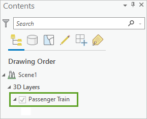
- In the Contents pane, right-click Passenger Train and click Properties.
The Layer Properties window appears.
- In the Layer Properties window, click the Source tab.
Geometry Type is set to 3D Object V2 (Multipatch). Any new features created in this layer will be 3D object features.
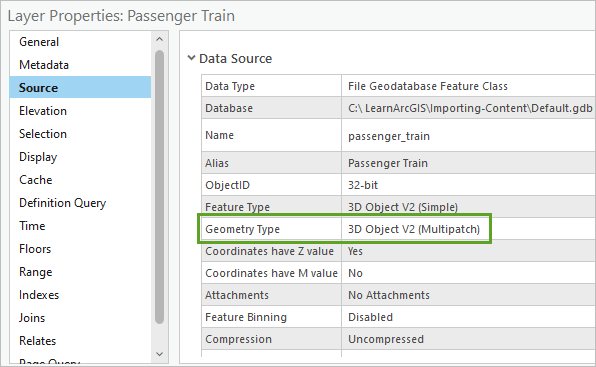
- Click Cancel to close the Layer Properties window.
Next, you'll add a feature to the Passenger Train layer.
- On the ribbon, click the Edit tab. In the Features group, click Create.

The Create Features pane appears.
- In the Create Features pane, click Passenger Train.
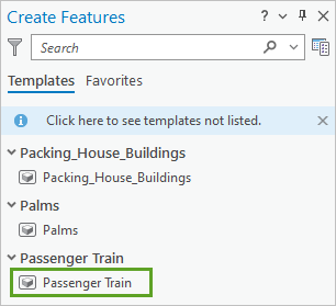
The Create Features pane now displays the available multipatch construction tools. You'll create a feature by importing a model.
- Click the Model File construction tool.

- Click the Add one or more models button.
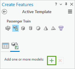
The Browse 3D model files window appears. You will use a GLB model for this feature, but it is possible to use any other accepted 3D object file type, including COLLADA, FBX, GLB, GLTF, and OBJ.
- In the navigation pane, under Project, expand Folders, Importing-Content, and Data_Files. Click the GLB folder and select the keio_5000_train.glb file.
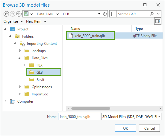
- Click OK.
In the Create Features pane, the model has been added to the active template. You'll adjust its size and rotation before adding it to the scene.
- In the Create Features pane, set the following parameters:
- For Size (Feet), set the Height (Z), Width (X), and Depth (Y) values to 18 ft.
- Expand Rotation (Degrees). Set the Angle (Z) value to 90 dd.
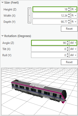
This method of altering the model is useful if you know in advance how the model needs to be modified relative to the scene. Other methods of freehand modifications are discussed later in this tutorial.
- In the local scene, move the pointer around the scene.
A train feature from the GLB file is attached to the pointer.
- Click to place the 3D model along the Southern California Regional rail line located to the south of West Stuart Avenue.
If you don’t place it precisely on the rail line, you can modify it later.
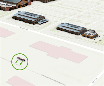
- On the ribbon, on the Edit tab, in the Tools group, click the Move tool.

The train feature is selected and arrows in x-, y-, and z-directions appear.
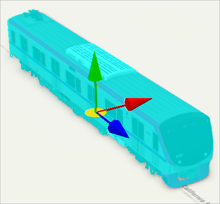
- Drag the colored arrows to move the model on each axis. Drag the centered yellow disc to move the model on all axes at once.
- On the editing toolbar, click the Finish button.

Tip:
Alternatively, press F2 to finish moving the model.
- On the Edit tab, in the Tools group, click the Rotate tool.

- Using the blue axis wheel, flip the train on its side.
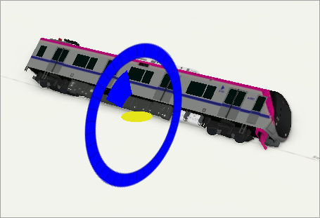
The train is already rotated correctly to match the rail line, so you'll undo your edit.
- On the editing toolbar, click the Cancel button.
The train is too small for the rest of the scene, so you'll make it larger.
- On the Edit tab, in the Tools group, click the Scale tool. On the axis, drag the yellow handle to make the train larger until it is a realistic size for the scene.
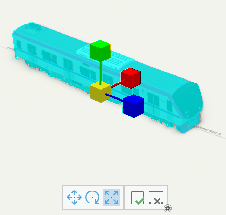
- On the editing toolbar, click the Finish button.
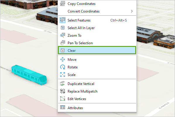
- Right-click anywhere on the scene and click Clear to clear the selection.
- On the ribbon, on the Edit tab, in the Manage Edits group, click Save.

- In the Save Edits window, click Yes.
The newly created Train feature is committed to the passenger_train feature class.
In this section, you added a 3D object feature layer and changed its dimensions using editing tools. Next, you will complete a similar process for a simple multipatch layer.
Place and interact with a model on a simple multipatch layer
Next, you'll add a model of a palm tree to the scene using a simple multipatch layer. The simple multipatch layer is the basis for the 3D object feature layer, so they have similar workflows. The main differences are that materials are not supported, and the features will have no georeferencing by default. Simple multipatch layers are useful for models that are more generic in nature, do not contain any materials, and are not the primary focus of a scene.
- In the Contents pane, right-click the Palms layer and click Properties.
The Layer Properties window appears.
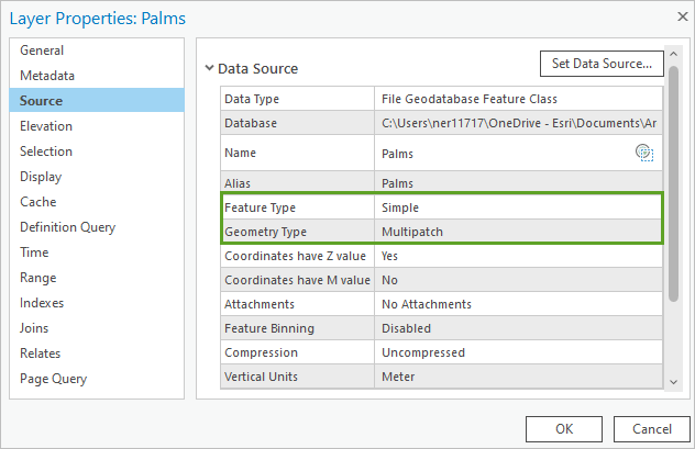
- In the Layer Properties window, click the Source tab.
Feature Type is set to Simple and Geometry Type is set to Multipatch.
- Click Cancel.
- On the ribbon, on the Edit tab, in the Features group, click Create.
The Create Features pane appears.
- In the Create Features pane, click the Palms template. Click Model File, and if necessary, click the Open the active template pane button.
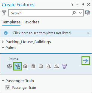
- Click the Add one or more models button.
The Browse 3D model files window appears.
- In the navigation pane, under Project, expand Folders, Importing-Content, and Data_Files. Click the FBX folder and select the palm.fbx file.
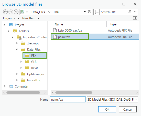
In this tutorial, the FBX format is used, but you can choose any acceptable simple multipatch format, such as 3DS, WRL, FLT, DAE, FBX, or OBJ.
- Click OK.
- Move the pointer to the scene but do not click the scene yet.
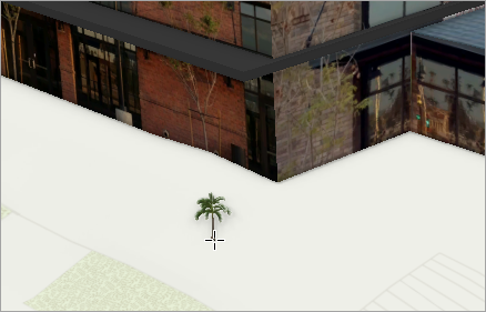
A palm tree model is attached to the pointer, but it is too small.
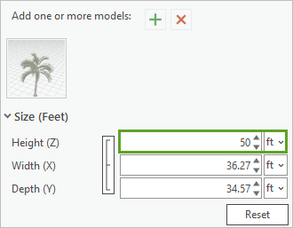
- In the Create Features pane, update the Height (Z), Width (X), and Depth (Y) values to 50 ft.
- Place several palm trees in the scene.
- In the Create Features pane, click the three connected bars next to the size properties.
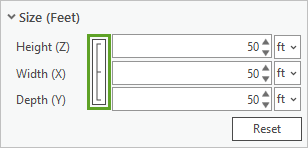
You are now able to set Height (Z), Width (X), and Depth (Y) properties independent of one another.
- Place several more palm trees in the scene with different size configurations.
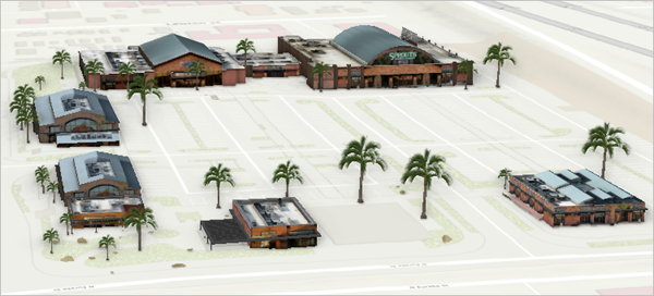
- When you're finished, save your edits and clear any active selection.
- Close the Create Features and Modify Features panes.
Read and add Revit.rvt (BIM) projects to ArcGIS Pro
Revit is a design and documentation platform that supports the design, drawings, and schedules required for building information modeling (BIM). You will explore the contents of a Revit model and add it to your scene.
- In the Catalog pane, right-click Folders and click Add Folder Connection.
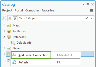
The Add Folder Connection window appears.
- In the navigation pane, under Project, expand Folders and Importing-Content. Click the Data_Files folder and select the Revit folder.
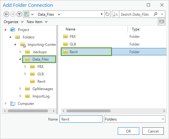
- Click OK.
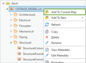
- In the Catalog pane, expand Folders, Revit, and COTTAGE_MODEL.rvt.
The entire COTTAGE_MODEL.rvt project is available directly as a data source without the need for conversion.
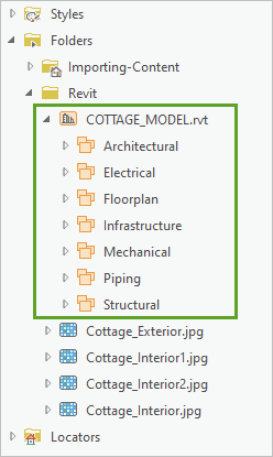
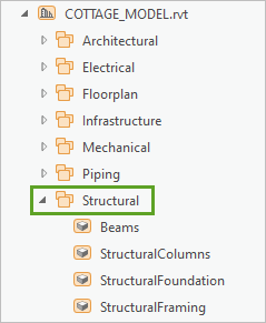
- Under COTTAGE MODEL.rvt, expand the Structural dataset.
The model consists of building elements organized by type. The Structural dataset includes beams, the foundation, framing, and columns of the building.
- Expand the Architectural dataset.
This category includes doors, furniture, and other architectural elements of the building.
- When you are done exploring the model, collapse any open datasets.
- In the Catalog pane, right-click COTTAGE_MODEL.rvt and click Add To Current Map.
Note:
You can also drag COTTAGE_MODEL.rvt onto the scene.
The model was added to the scene, but it is not visible. It has no coordinate system information yet, so it may appear in the middle of your scene or in the middle of the ocean. Next, you'll georeference the model to place it in the correct location.
Georeference a Revit.rvt (BIM) model
When 3D models from third-party applications are added to ArcGIS Pro, they are often not georeferenced, which means that they have no coordinate system. You'll use ArcGIS georeferencing tools to update and place a building model in the correct coordinate space.
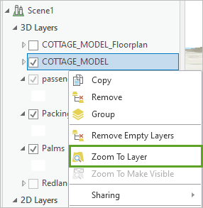
- In the Contents pane, right-click COTTAGE_MODEL and click Zoom To Layer.
The model appears on a blue background. The coordinate location listed below the scene indicates a location very close to 0 degrees east and 0 degrees north.
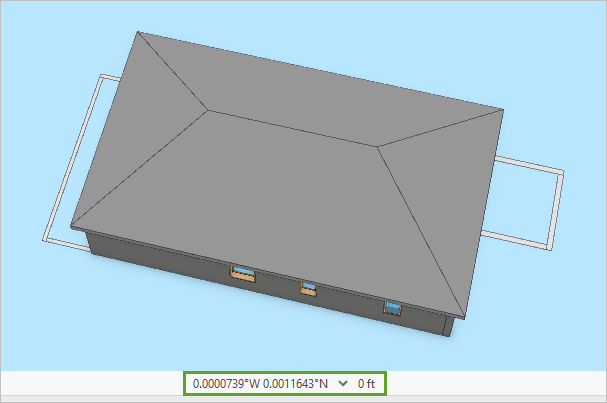
Because the model has no coordinate system defined, it appears at the origin of the map's coordinate system, a place near the west coast of Africa. You'll define a coordinate system for the layer and georeference it to its correct location.
- In the Contents pane, right-click Packing_House_Buildings and click Zoom To Layer.
- Pan to the south and zoom to an empty area between West Stuart Avenue and the rail line.
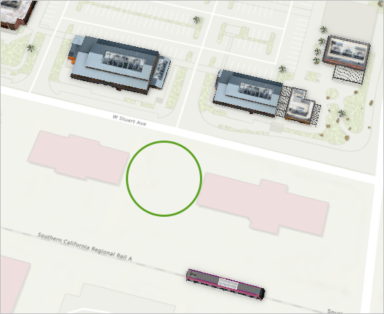
You'll georeference the building model to place it in this location. Ensure that your chosen location is in the center of the scene.
- In the Contents pane, click COTTAGE_MODEL to select the layer.
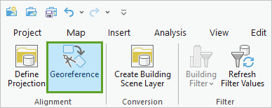
- On the ribbon, click the BIM Data tab. In the Alignment group, click Georeference.
A window appears, asking if you want to update the data source with the current map's spatial reference.
- Click OK.
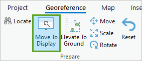
- On the ribbon, on the Georeference tab, in the Prepare group, click Move To Display.
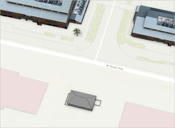
The building appears in the scene. You will adjust its size and rotation.
- On the ribbon, on the Georeference tab, in the Prepare group, click Scale.
- Using the axes, adjust the building's size until it matches the surrounding buildings.
Tip:
To tilt the scene, on the ribbon, click the Map tab. In the Navigate group, click Explore. When you are done tilting the scene, return to the Georeference tab on the ribbon. In the Prepare group, click the Scale button.
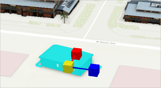
- On the ribbon, on the Georeference tab, in the Prepare group, click Rotate. Rotate the model until it is parallel with the street.
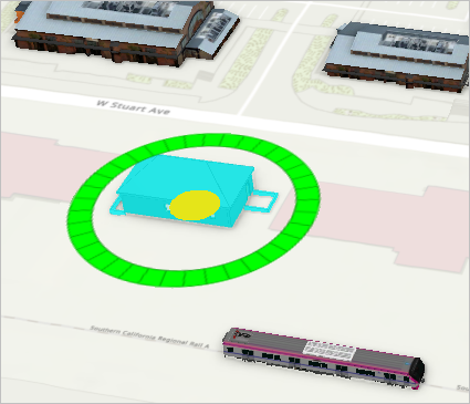
- If necessary, use the Move tool to reposition the model.
- When you finish positioning the model, on the Georeference tab, in the Save group, click Save.
The model may disappear for a moment while it updates.
- When the building has reappeared in its new position, click the Close Georeference button to exit the georeferencing process.

- Save the project and close ArcGIS Pro.
When working with external or imported content, it is important to understand the purpose of the scene you are creating. Understanding your assets allows you to place them on the appropriate 3D layer to best display their intended purpose.
Simple multipatch layers are best used for models that are designed to fill in the view. They are typically less robust than the main models and do not need to be georeferenced. The 3D object feature layer is best used for 3D features that are visually important to your scene and are georeferenced. These layers support physically based rendering (PBR) materials and are more complex than other models in your scene. Revit models are useful when you need to provide more CAD information to users. These 3D models display native BIM data when imported. They can be georeferenced in the scene.
