Create network features
To begin, you'll review the provided data and its structure. Then you'll modify feature templates and use editing tools to create connection points, medium voltage lines, a fuse, and a transformer. You'll then validate the network topology and save your edits.
An engineer at the Public Works Department has provided you with a design for a service drop within a new residential development. You'll follow the parameters of this design to test the functionality of the utility network.
Modify feature templates
You'll create new features with feature templates. First, however, you'll modify the feature templates to ensure they have the correct attributes according to the provided design.
- Download the Auburn Utility Network project package.
A file named Auburn_Utility_Network.ppkx is downloaded to your computer.
Note:
A .ppkx file is an ArcGIS Pro project package and may contain maps, data, and other files that you can open in ArcGIS Pro. Learn more about managing .ppkx files in this guide.
- Locate the downloaded file on your computer. Double-click Auburn_Utility_Network_project.ppkx to open it in ArcGIS Pro.
- If prompted, sign in with your ArcGIS account.
Note:
If you don't have access to ArcGIS Pro or an ArcGIS organizational account, see options for software access.
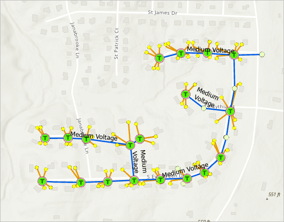
The project opens in ArcGIS Pro. It contains part of the electric utility network in Auburn, Alabama.
- In the Contents pane, click the arrow next to the Electric Distribution Device layer to expand it.
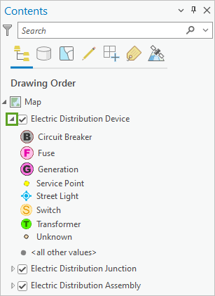
Utility network data is structured into relatively few layers, but classification is built within each layer using the Asset Group and Asset Type fields. The Electric Distribution Device layer shows a unique symbol for each Asset Group value (for example, Circuit Breaker, Fuse, Generation, and so on) and each of these values is further subdivided by Asset Type values. This classification scheme limits the number of layers, allowing for faster performance.
The Asset Group field is also the subtype field for each layer. Subtypes are a method of subcategorizing layers that allows each asset group to behave more like independent layers. For example, each subtype may have different connectivity, relationship, or topology rules associated with it.
Note:
Read more about the structure of a utility network and utility network feature classification.
Next, you'll begin creating the features described in the engineer's design.
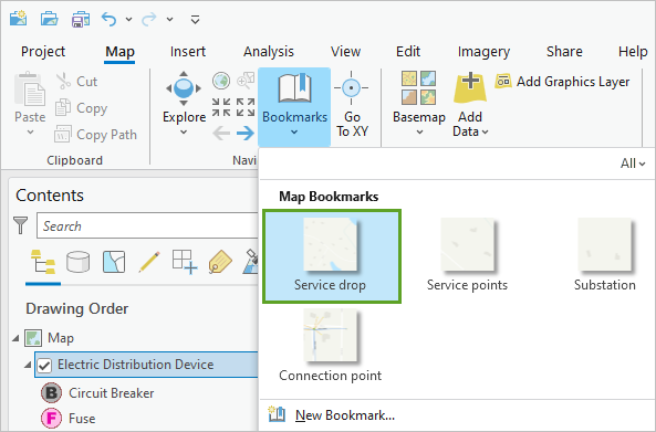
- On the ribbon, click the Map tab. In the Navigate group, click Bookmarks and choose Service drop.
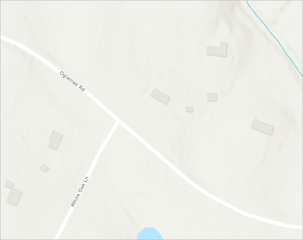
The map moves a short distance to the east, to the intersection of Ogletree Rd. and White Oak Ln. This is the location indicated in the design where a new service drop must be added.
Before you begin editing, you'll verify that your snapping environment is properly configured. Snapping helps to ensure that proper connectivity is established between network features.
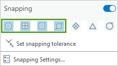
- On the ribbon, click the Edit tab. In the Snapping group, click the lower half of the Snapping button.

- Verify that Snapping is enabled, as well as the first four snapping options: Point, Endpoint, Vertex, and Edge.
- On the ribbon, in the Features group, click Create.

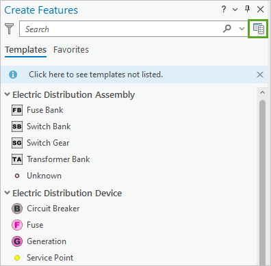
The Create Features pane appears. It lists feature templates for all the subtypes in the utility network. You can use these templates to create new features prepopulated with the default attributes for each subtype.
You'll create features using several of these templates. However, the design you are following calls for single-phase electric lines energized with phase B. This means that some of the default attributes provided by the feature templates must be changed. You can edit the attributes after features are created; however, to save time, you'll modify the templates beforehand, so all new features have the correct attributes.
- At the top of the Create Features pane, click the Manage Templates button.
The Manage Templates pane appears.
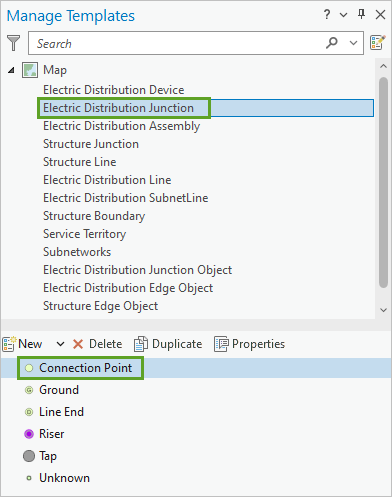
- In the Manage Templates pane, click Electric Distribution Junction and double-click Connection Point.
The Template Properties window appears.
- In the Template Properties window, click the Attributes tab to display the default attributes used with the Connection Point template.
- In the attributes list, make the following updates:
- For Phases Built, choose B.
- For Phases Normal, choose B.
- For Phases Current, choose B.
- For phasesenergized, choose B.
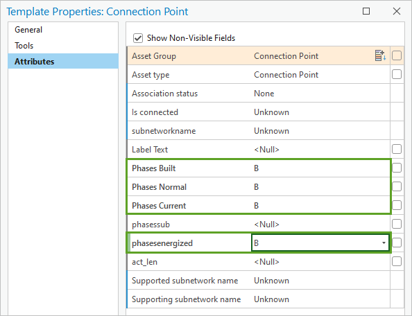
All new features created with the Connection Point template will now use phase B.
- Click OK.
Next, you'll update the templates for the other features you will be working with in this tutorial.
- In the Manage Templates pane, click Electric Distribution Line and double-click Medium Voltage to open its template properties.
- In the Template Properties window, click the Attributes tab and update the following attributes:
- For Asset type, choose Single Phase Overhead.
- For Phases Built, choose B.
- For Phases Normal, choose B.
- For Phases Current, choose B.
- For phasesenergized, choose B.
- Click OK to close the window.
- In the Manage Templates pane, double-click Low Voltage and update the following attributes:
- For Phases Built, choose B.
- For Phases Normal, choose B.
- For Phases Current, choose B.
- For phasesenergized, choose B.
- Click OK.
- In the Manage Templates pane, click Electric Distribution Device. Update the Circuit Breaker, Fuse, Service Point, and Transformer templates with the following attributes:
- For Phases Built, choose B.
- For Phases Normal, choose B.
- For Phases Current, choose B.
- For phasesenergized, choose B.
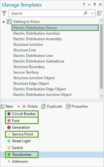
Now when you add features to these layers, the correct attributes will be automaticaly entered.
- Close the Manage Templates pane.
Create features
With the default attribute values set, you can create features without the need to update attributes afterward. You'll add several new connection points and medium voltage lines to model a new development east of the existing network.
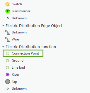
- In the Create Features pane, under Electric Distribution Junction, click the Connection Point template.
Tip:
If you can't find the Create Features pane, on the ribbon, click the Edit tab. In the Features group, click Create.
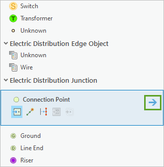
- On the Connection Point template, click the Open the active template pane arrow to view the attributes set for this template.
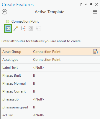
The Phases Built, Phases Normal, Phases Current, and phasesenergized values should all be set to B.
- At the top of the pane, click the Point button to choose the method of construction.
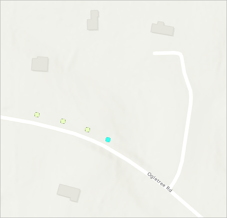
- On the map, click to place four connection points in a line along the north side of Ogletree Rd.
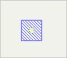
- Zoom in to one of the points until a hatched rectangle appears around the point.
Tip:
To pan on the map while editing, press and hold the C key while dragging the pointer.The rectangle is a dirty area. The utility network creates polygon features called dirty areas to track all the edits and errors in the dataset.
- In the Contents pane, expand the Auburn Utility Network layer.
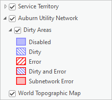
The Dirty Areas sublayer contains five kinds of dirty areas. In this tutorial, you'll only encounter the second type: Dirty, which indicates that an edit has occurred that is not yet reflected in the network topology. Every utility network has a network topology. It maintains the connectivity of features to ensure that the commodity (in this case electricity) can flow correctly through the utility network. The network topology allows you to perform traces and integrity checks on the data against a collection of rules.
You'll validate the network topology to include your new features. This will remove the dirty area.
- On the ribbon, click the Utility Network tab. In the Network Topology group, click the lower half of the Validate button and choose Entire extent.
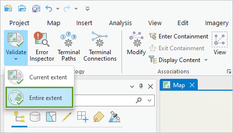
After validation has completed, the dirty areas around each of the new connection point features disappear.
- Zoom out until you can see all four connection points.
Next, you'll add a medium voltage line to connect each connection point. However, before you create the line features, you'll check the rules of the utility network to determine if you are allowed to connect medium voltage lines to connection points. If you are not allowed, Error dirty areas will appear when you create the features.
- In the Contents pane, right-click Auburn Utility Network and click Properties.
- In the Layer Properties window, click the Network Properties tab. Expand the Rules section.
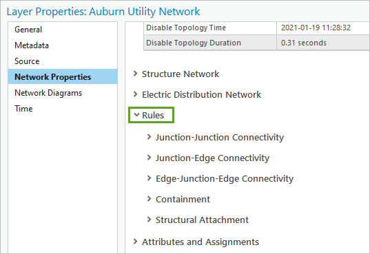
Network rules dictate which network features can connect or associate in the utility network. All rules are evaluated when the network topology is validated. You're interested in connecting line features to point features, so you'll review the junction-edge rules.
- Expand the Junction-Edge Connectivity section. Scroll through the table until you find rule 482.
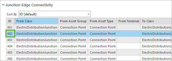
This rule allows Electric Distribution Junction features with an Asset Group value of Connection Point and an Asset Type value of Connection Point to connect to Electric Distribution Line features with an Asset Group value of Medium Voltage and an Asset Type value of Single Phase Overhead.
- Close the Layer Properties window.
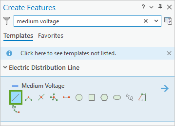
- At the top of the Create Features pane, click the Back button. In the search bar, type medium voltage.
- Under Electric Distribution Line, click the Medium Voltage template and choose the Line tool.
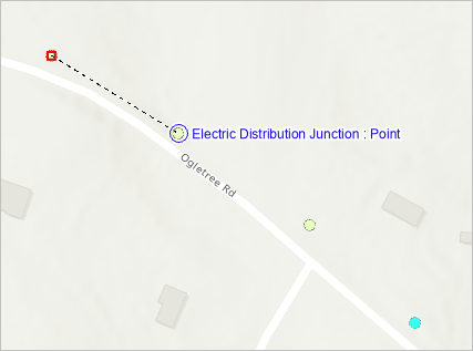
- On the map, point to the first (leftmost and westernmost) connection point. When the snapping ToolTip says Electric Distribution Junction : Point, click to begin drawing a line connected to the point. Snap to the next point and double-click to end the line segment.
Note:
The snapping rules configured for the map are overridden by any utility network rules. You cannot snap a feature to another feature if a rule does not exist to support connectivity between them.
A dirty area rectangle appears around the new line segment.
- Draw two more individual line segments to connect the rest of the points.
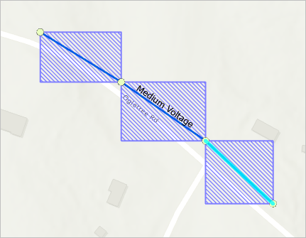
Next, you'll validate the network topology to clean the dirty areas.
- If necessary, zoom out until you can see all three dirty areas fully.
By default, the Validate command only validates dirty areas within the current map extent.
- On the ribbon, on the Utility Network tab, in the Network Topology group, click the top half of the Validate button.

The dirty areas disappear.
Next, you'll clear the selection and save your edits.
- On the ribbon, click the Edit tab. In the Selection group, click the Clear button.

- In the Manage Edits group, click the Save button.

- In the Save Edits window, click Yes.
Add a fuse and transformer
Next, you'll create fuse and transformer features, using the Point At End of Line construction tool.
- On the map, zoom to the last (rightmost and easternmost) connection point along Ogletree Rd.
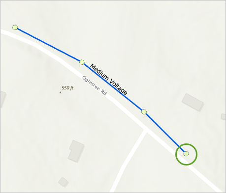
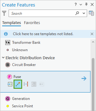
- In the Create Features pane, clear the search bar. Under Electric Distribution Device click the Fuse template and choose the Point At End of Line tool.
Next, you'll create a fuse using an offset from the selected connection point.
- Snap to the last connection point. Right-click the map to view more editing options and click Distance.
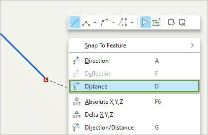
The Distance window appears.
- In the Distance window, ensure that the unit of measurement is set to ft and type 3.
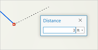
- Press Enter to apply the distance constraint.
On the map, a construction line constrained to 3 feet extends from the connection point. You may need to zoom in further to see the construction line.
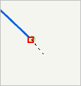
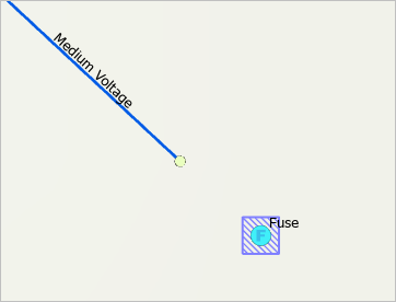
- Double-click the map to add a new fuse southeast of the selected connection point.
A new fuse feature appears on the map.
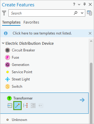
- In the Create Features pane, under Electric Distribution Device, click the Transformer template and choose the Point At End of Line tool.
- On the map, click the fuse point. Right-click the map and click Distance.
- Enter a distance of 3 ft and press Enter. Double-click the map to add a new transformer to the southeast of the fuse feature.
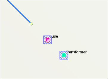
Next, you'll clear the selection, validate the topology, and save the edits.
- On the ribbon, click the Edit tab. In the Selection group, click the Clear button.
- On the Utility Network tab, click the Validate button.
- On the Edit tab, click the Save button, and click Yes to confirm saving the edits.
Run a connected trace
Next, you’ll run a connected trace to verify that the new features are connected as expected. A trace spans out from a starting point along all paths of connected features and objects until it reaches either a barrier or the end of a path. The result of a trace is a set of selected features.
- On the ribbon, click the Map tab. In the Navigate group, click Bookmarks, and click Service drop.
The map zooms to the Service drop bookmark. You'll begin by defining the starting point for a connected trace.
- On the ribbon, click the Utility Network tab. In the Tools group, click the lower half of the Trace button and choose Starting Points.
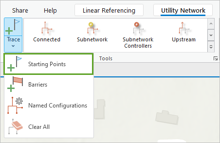
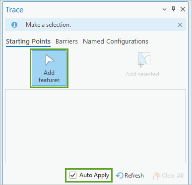
The Trace pane appears with the Starting Points tab selected.
- In the Trace pane, ensure the Add features button is active (highlighted in blue) and the Auto Apply check box is checked.
- On the map, click any one of the connection points to set the start location for the trace.
A green circle appears on the map to mark the starting point.
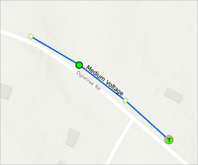
In the Trace Locations pane, an entry is added identifying the starting point feature.
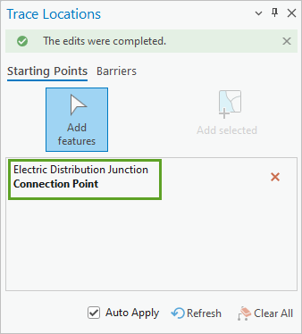
Next, you'll choose the trace type.
- On the ribbon, in the Tools group, click Connected.

The Geoprocessing pane appears, open to the Trace tool. The tool's parameters are configured with the default settings for a connected trace, which will confirm that features are connected as expected.
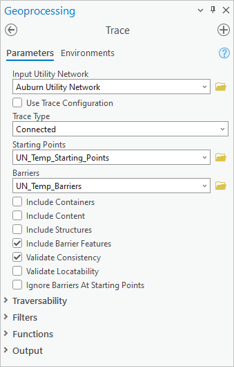
- Click Run.
When the trace is completed, seven features are selected on the map: the four points and the three lines you created earlier.
- In the Contents pane, click the List By Selection tab to verify which features are selected.
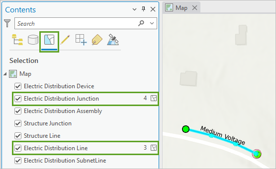
The number of selected features appears next to each layer name.
- Click the List By Drawing Order tab to return to the default view of the Contents pane. Do not clear the selection.
- On the map, zoom to the fuse and transformer.
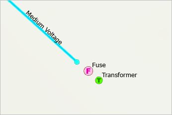
These features weren't traced because they are not connected to the others.
- Validate the topology and clear the selection.
- On the Quick Access Toolbar, click Save to save the project.

You have modified feature templates and created new features. You validated the network topology and ran a connected trace. You also learned about the utility network data structure, dirty areas, network rules, and editing tools. Next, you'll learn how to connect the fuse and transformer to the other features.
Work with associations
Not all features in the utility network are physically connected in the map. Associations exist to model another way that features are related to one another. Next, you'll create connectivity associations to connect the transformer and fuse to the medium voltage lines. You'll create structural attachment associations to connect these features to a pole. And you'll create a containment association to set a circuit breaker as content inside of a subnetwork container.
You'll also create low voltage lines extending to nearby houses and modify their terminal connections to ensure they are correctly connected to the terminal.
Create connectivity associations
You created the connection point, fuse, and transformer features so they are displayed at a distance of 3 feet from one another. In reality, they are all geometrically coincident, but if you drew them all in the same location, the map would be difficult to read. Next, you'll model connectivity associations between these three features. This will ensure that they are considered connected by the network topology even though the features are not touching on the map.
- On the ribbon, click the Utility Network tab. In the Associations group, click Modify.

- In the Modify Associations pane, click Add features.
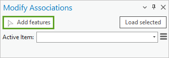
The Add features tool will display a different arrow icon as you move over the map.
- Click the connection point feature.
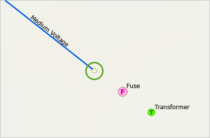
In the Modify Associations pane, the Active Item menu is populated with the connection point feature.
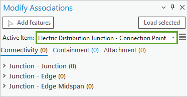
You'll create a connectivity association between the connection point and the fuse feature.
- Expand the Junction - Junction section. Next to the Add selected button, click the add features button.
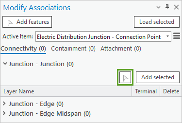
- On the map, click the fuse feature.
The fuse is added to the Junction - Junction section of the pane with a green bar to indicate it is a new association.
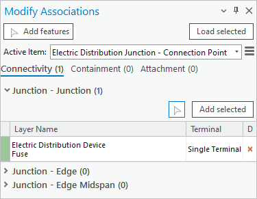
- In the Modify Associations pane, click Apply.
Dirty areas appear around the connection point and fuse features. Next, you'll create a connectivity association between the fuse and the transformer.
- In the Modify Associations pane, in the Junction - Junction section, right-click Electric Distribution Device Fuse and choose Modify Associations.
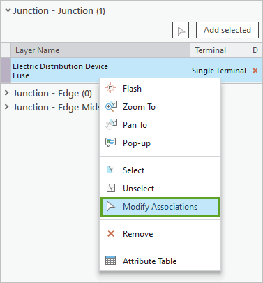
The Active Item updates to the fuse and the connectivity associations for the fuse are listed. The fuse has one connectivity association with the connection point. This is the association you created in the previous steps.
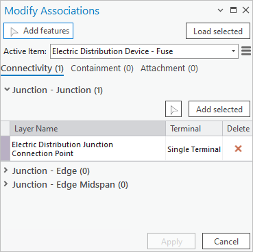
- In the Junction - Junction section, click the add features button and click the transformer feature on the map.
The transformer is added to the Junction - Junction section.
- Next to Electric Distribution Device Transformer, ensure that Terminal is set to High.
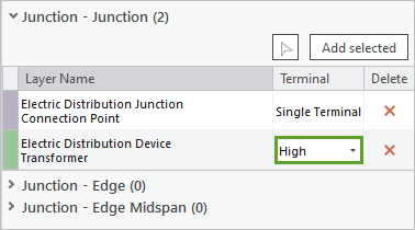
Terminals represent defined locations or ports on devices or other junction objects, through which electricity flows in and out. Terminals create internal paths that control how electricity can flow through the device at different states. According to the design you are following, electricity should flow from the fuse into the transformer via the high side terminal.
- Click Apply.
- On the ribbon, in the Associations group, click View to turn View Associations Mode on.

View Associations Mode displays connectivity associations on the map as dashed brown lines.
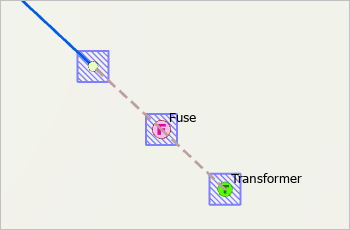
Note:
Connectivity associations are shown for the current map extent only. If you move to a different area, you must turn View Association Mode off and on again to view associations for the new area.
- On the ribbon, in the Associations group, click the View button to turn off View Associations Mode.
- Ensure that all three dirty areas are within view and validate the topology.
The dirty areas disappear from the map.
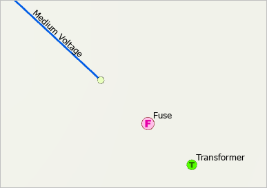
- Save your edits.
Modify terminal connections
Now that the transformer is connected to the medium voltage line via connectivity associations, you'll create service points for the nearby houses. You'll connect them to the transformer with low voltage service lines and ensure that they connect via the correct terminal.
- Zoom to the Service Points bookmark.
The map zooms out. On the basemap, three houses are visible to the north of the new features. These houses represent the new development that requires service. You'll create a service point feature for each house and connect them to the transformer with low voltage lines.
- Reopen the Create Features pane. Under Electric Distribution Device, click the Service Point template and choose the Point tool.
- Click the map to add three service points, each close to one of the three homes visible on the basemap.
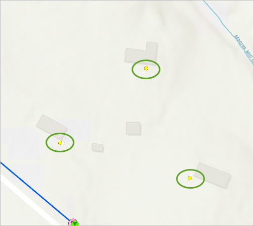
- In the Create Features pane, search for and click Low Voltage template.
- Click the Radial tool.
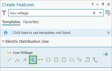
This tool will create line features originating from a common center.
- On the map, zoom to and click the transformer feature.
- Zoom out until you can see the three service points next to homes. Click one of the service points.
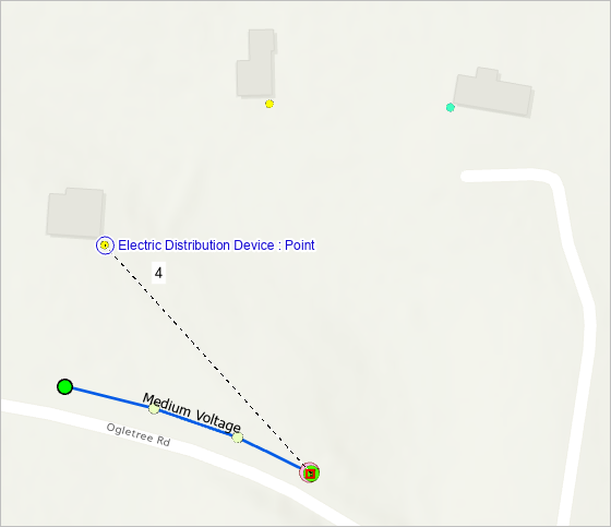
Note:
Based on where you added the connection points, the layout of your points and lines may be different than what is shown in the images.
- Click the remaining two service points. For the final point, double-click to complete the connections.
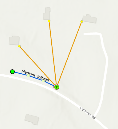
Dirty areas appear around the three new lines.
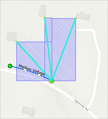
Next, you'll verify that the low voltage lines are associated with the proper terminal of the transformer.
- On the ribbon, click the Utility Network tab. In the Network Topology group, click Terminal Connections.
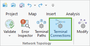
The Modify Terminal Connections pane appears.
- In the Modify Terminal Connections pane, ensure the Select a line feature button is active (highlighted in blue).
- On the map, click one of the low voltage lines.
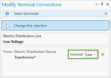
The low voltage line feature is added to the Modify Terminal Connections pane. One terminal connection is listed, for the transformer device. There is an asterisk next to Transformer, indicating that a terminal choice is required but not yet defined.
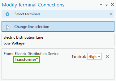
High is the default choice, but it is shown in red to indicate it is an invalid choice. In this case, it is invalid because the fuse is already connected to the transformer via the high side terminal. You'll connect the line with its low side terminal instead.
- For Terminal, choose Low.
- Click Apply.
- In the same manner, click the remaining lines and set their Terminal attribute to Low.
- Validate the topology, clear the selection, and save your edits.
Create structural attachment associations
The fuse and transformer you created won't sit on the ground or float in space: in the real world, they'll be attached to a pole. Even though electricity doesn't flow through poles, they play an important role in delivering electricity. A utility network is divided into the domain network (in this case, the Electric Distribution Network), which contains the devices, lines, junctions, and other objects that the commodity flows through, and the structure network, which includes poles, vaults, manholes, and other physical structures that the commodity does not flow through but which support the domain network.
Features in the domain network can be connected to features in the structure network with structural attachment associations. Next, you'll create a pole feature and attach the connection point, fuse, and transformer to it with a structural attachment association.
- Zoom to the transformer feature.
- Reopen the Create Features pane. Search for and click the Pole template. Choose the Point At End of Line tool.
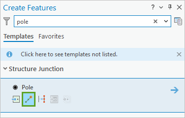
- Add a pole feature 6 feet to the west of the transformer.
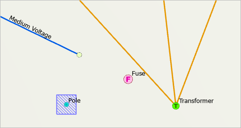
Next, you'll create a structural attachment association between the pole and the nearby connection point, fuse, and transformer.
- Ensure that the pole feature is still selected. Reopen the Modify Associations pane.
Tip:
If you can’t find the Modify Associations pane, on the ribbon, click the Utility Network tab. In the Associations group, click Modify.
- In the Modify Associations pane, click Load selected.
Active Item in the Modify Associations pane is updated with the pole structure junction.
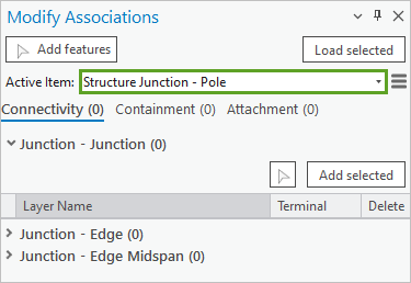
Structural attachment associations are managed on the Attachment tab.
- Click the Attachment tab. Expand the Attachments section and click the add features button.
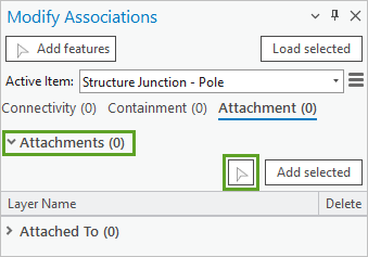
- On the map, click the connection point, fuse, and transformer features.
All three features are added to the pane with green bars to indicate they are new attachments.
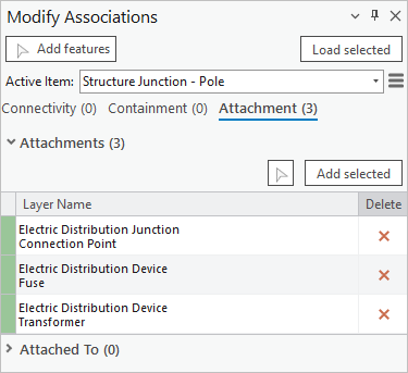
- In the Modify Associations pane, click Apply.
Dirty areas appear around the three features.
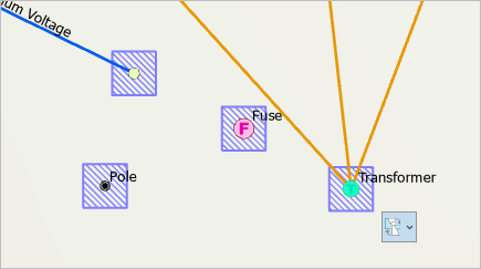
- Close the Modify Associations pane.
- Validate the topology, clear the selection, and save your edits.
The connection point, fuse, and transformer are now connected to the pole with a structural attachment association. You'll review the associations using View Associations Mode.
- On the ribbon, click the Utility Network tab. In the Associations group, click View.
Dashed lines appear on the map. Brown dashed lines represent connectivity associations and green dashed lines represent structural attachment associations.
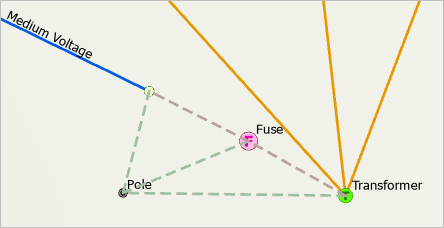
- Click View again to turn off View Associations Mode.
The dashed lines disappear from the map.
Run a connected trace
Next, you'll run another connected trace to see the effects of the associations you've created so far.
- On the ribbon, click the Utility Network tab. In the Tools group, click the upper half of the Trace button to reopen the Trace pane.
- In the Trace pane, confirm that a Connection Point feature is listed, indicating that a starting point is still set.
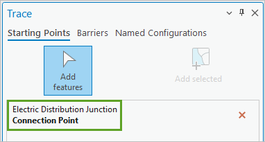
Note:
If no starting point is listed, click the Add features button and click any of the connection points along Ogletree Rd.
- On the ribbon, in the Tools group, click Connected.
The Geoprocessing pane reappears and is open to the Trace tool.
- In the Geoprocessing pane, click Run.
- Zoom in and out on the map to explore which features were selected by the trace.
All the new features are selected except for the pole.
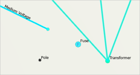
The connectivity trace honored the connectivity associations and traced from the medium voltage lines along Ogletree Rd. out to the houses, via the fuse and transformer. It did not include the pole because the Include Structures check box was unchecked in the Trace tool parameters.
The results of the connected trace show that the new features are correctly connected.
- Clear the selection.
- Close the Geoprocessing and Trace panes.
Create a container and subnetwork controller
Next, you'll create a substation feature. The real substation for this area of Auburn is placed elsewhere, about 2 miles away, and it wasn't included in the sample data provided by the consultant. Since you've been tasked with exploring the capabilities of a utility network, you'll create a fake substation closer to your existing features to test containment associations.
A substation is an example of a container, which is a network feature that contains other features. Typically, container features are visible on the map, while their content features are hidden, which helps to control map clutter. Content is connected to its container with a containment association.
- Zoom to the Substation bookmark.
The map zooms to an area north of Ogletree Rd.
- Reopen the Create Features pane. Search for and click the Substation template. Choose the Polygon tool.
- Draw a rectangle on the map, a little larger than the buildings visible on the basemap. Double-click to complete the sketch.
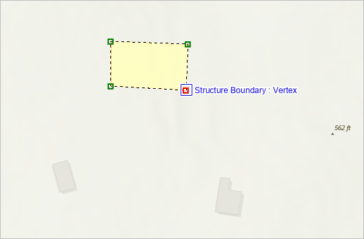
Next, you'll enter containment edit mode and add content to the substation container.
- On the ribbon, click the Utility Network tab. In the Associations group, click Enter Containment.

- On the map view, click the substation feature.
Selecting the substation places the system in containment edit mode and updates the map extent to the selected container feature. The feature is selected and surrounded by a dashed outline, which provides a visual reminder that you are in containment edit mode. When you are in this mode, any features you create are added to the active container as content.
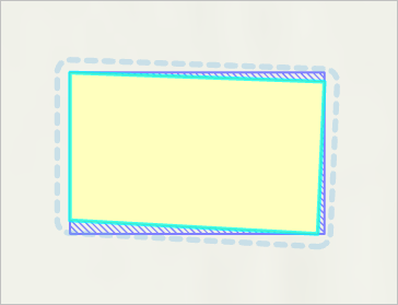
- In the Create Features pane, search for and click the Circuit Breaker template under Electric Distribution Device. Choose the Point tool.
- On the map, click inside the substation polygon to place a new circuit breaker feature.
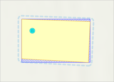
- Confirm that the circuit breaker feature is selected.
- On the ribbon, click the Edit tab. In the Selection group, click Attributes.

The Attributes pane appears, listing the attributes for the new circuit breaker feature. The Association status attribute is set to Content. This is because the feature was created within the substation boundary while in containment edit mode.
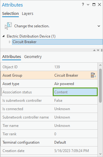
Certain types of features are permitted to become subnetwork controllers. Subnetwork controllers define the origin of a subnetwork. They act as either a source or a sink to determine how resources flow through the network. In this scenario’s configuration, circuit breakers and transformer devices can be set as subnetwork controllers. Next, you'll set the new circuit breaker as a subnetwork controller.
- On the ribbon, click the Utility Network tab. In the Subnetwork group, click Modify Controller.

The Modify Subnetwork Controller pane appears.
- Ensure that the circuit breaker feature is still selected. In the Modify Subnetwork Controller pane, click the Add selected button.
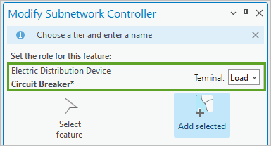
The circuit breaker feature appears in the pane.
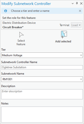
- In the Modify Subnetwork Controller pane, make the following changes:
- For Tier, ensure that Medium Voltage is selected.
- For Subnetwork Controller Name, type Ogletree Substation.
- For Subnetwork Name, type RM1001.
Note:
If you leave the Subnetwork Name field blank, an ID value will be assigned when you click Apply. When creating a subnetwork, provide a descriptive name, as it will be used to represent the subnetwork in other parts of the system.
- Click Apply.
- Close the Modify Subnetwork Controller pane.
You've now configured the circuit breaker as a subnetwork controller. You'll review its attributes to verify the changes made to the feature.
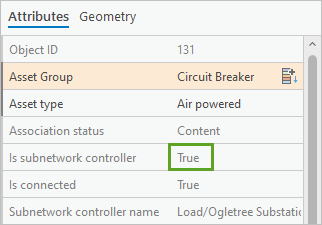
- Ensure that the circuit breaker feature is still selected. Reopen the Attributes pane.
Tip:
If you can't find the Attributes pane, on the ribbon, click the Edit tab. In the Selection group, click Attributes.
In the Attributes pane, the Is subnetwork controller attribute is set to True.
- On the Utility Network tab, in the Associations group, click Exit Containment.

Features created after this will no longer be set as content.
- Validate the topology, clear the selection, and save your edits.
- Save the project.
You have now connected the medium voltage lines to the service points on each house. You achieved this by creating new features and connecting them with terminals, connectivity associations, and structural attachment associations. You also created a substation and a circuit breaker inside it. These two features are associated with a containment association. Next, you'll connect the substation to the other assets.
Work with subnetworks and tracing
A subnetwork is a collection of lines, devices, and junctions that all connect to the same subnetwork controller or controllers. A utility network is typically composed of multiple subnetworks that can be altered by opening and closing devices such as switches and valves. The existence of a subnetwork allows you to perform subnetwork analysis and understand the flow of commodities. It is the subnetwork that drives tracing events, network diagrams, and provides techniques for network visualization (for example, creation of circuit maps).
Next, you'll connect features to the substation, create a subnetwork, and run a subnetwork trace.
Connect features to the substation
You'll create medium voltage lines to connect the Ogletree substation to the existing features that were provided by the consultant and the new features you created in this tutorial.
- Zoom out until you can see all the features on the map.
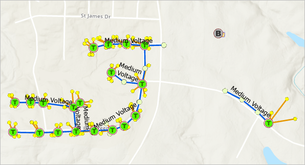
- In the Create Features pane, search for and click the Medium Voltage template. Choose the Line tool.
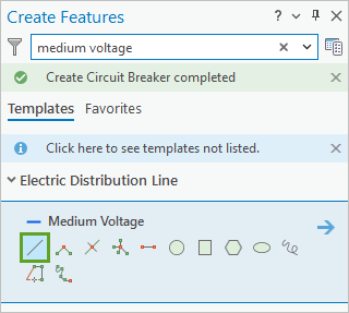
- On the map, click the first (leftmost and westernmost) connection point on Ogletree Rd. Double-click the circuit breaker feature to create a new line feature.
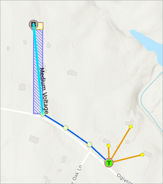
Note:
If you are unable to use the line construction tool, on the ribbon, click the Map tab. In the Navigate group, click Explore. Try to draw the line again.
- Zoom to the Connection point bookmark.
The map updates and displays a connection point near the intersection of Wrights Mill Rd. and Estate Ave.
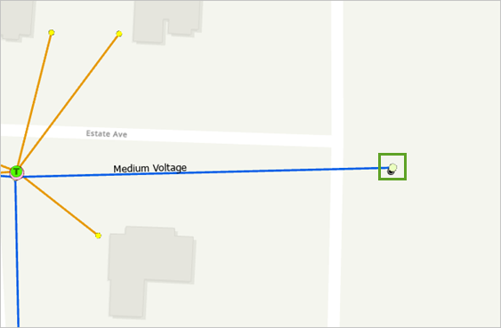
- Click the connection point feature. Zoom out and double-click the circuit breaker feature to create another new medium voltage line.
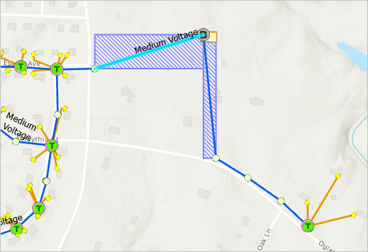
Next, you'll ensure that both new lines are associated with the correct terminal of the circuit breaker to properly model the junction-edge connectivity of the features.
- Close the Create Features pane and reopen the Modify Terminal Connections pane.
Tip:
If you can't find the Modify Terminal Connections pane, on the ribbon, click the Utility Network tab. In the Network Topology group, click Terminal Connections.
- In the Modify Terminal Connections pane, ensure that either Select a line feature or Change line selection is active and select either of the new lines on the map.
- For Terminal, choose Load.
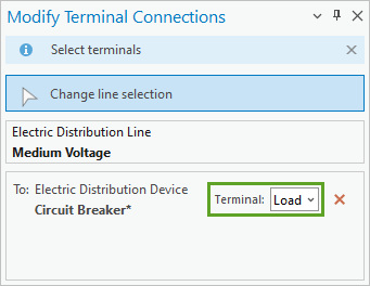
- Click Apply.
- On the map, click the other new line.
- In the Modify Terminal Connections pane, for Terminal, choose Load. Click Apply.
- Close the Modify Terminal Connections pane.
- Validate the topology, clear the selection, and save your edits.
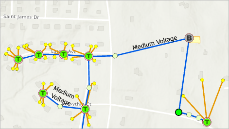
Create a subnetwork
Next, you'll create a subnetwork. You have already begun the creation of a subnetwork by setting the circuit breaker as a subnetwork controller, establishing it as a source for a subnetwork. To complete the process, you'll use the Find Subnetwork pane.
- On the ribbon, click the Utility Network tab. In the Subnetwork group, click Find.

The Find Subnetworks pane appears.
- In the Find Subnetworks pane, expand the Filter section.
- Click the Subnetworks Table tab and click the Filter button.
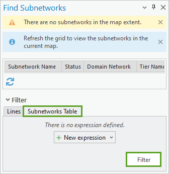
A table appears at the top of the pane, listing the RM1001 subnetwork. This name was defined earlier, in the Modify Subnetwork Controller pane.
- Right-click the RM1001 row and click Update Subnetwork.
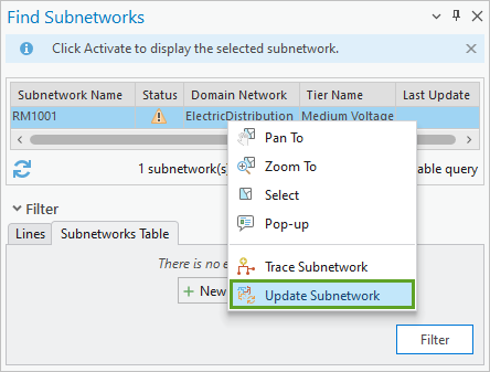
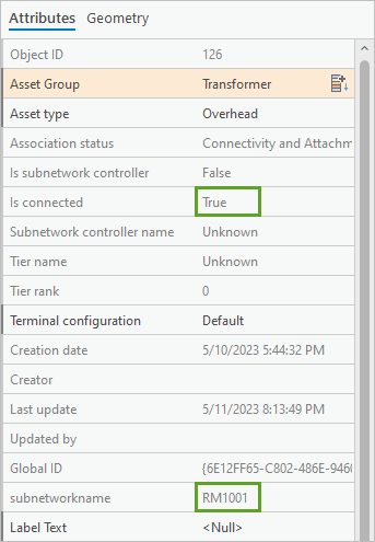
This process completes the creation of the RM1001 subnetwork; it validates feature connectivity and populates the subnetwork name and Is connected attribute on all connected features. No changes are visible on the map, but you'll verify the changes by reviewing the attributes of the transformer feature.
- Zoom to the transformer feature along Ogletree Rd.
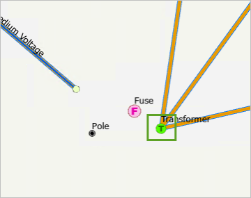
- On the ribbon, click the Edit tab. In the Selection group, click Select.
- On the map, click the transformer feature to select it.
- Reopen the Attributes pane.
The Is connected value is True and the subnetworkname value is RM1001.
- Close the Attributes pane.
The update subnetwork process also created a new feature in the SubnetLine feature class to represent the lines of the selected subnetwork.
- Zoom out until you can see all the map's features and clear the selection.
- In the Contents pane, uncheck the box next to Electric Distribution Line to turn this layer off. Turn on the Electric Distribution SubnetLine layer.
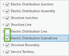
The map updates to display the Electric Distribution SubnetLine layer, representing the RM1001 subnetwork.
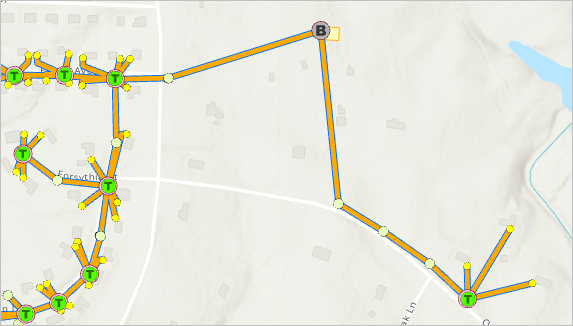
Electric Distribution SubnetLine is a read-only, system-provided feature class that is useful for gaining a high-level view of the subnetwork. It can be labeled, symbolized, and published to create quick subnetwork maps (circuit maps).
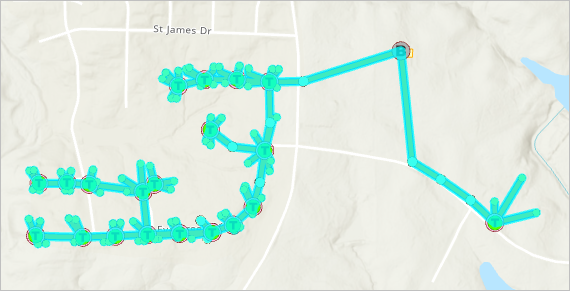
- On the map, click any part of the orange line.
The entire subnetwork is selected. All the orange lines represent a single feature.
- Clear the selection.
- In the Contents pane, turn on the Electric Distribution Line layer and turn off the Electric Distribution SubnetLine layer.
Run a subnetwork trace
Next, you'll run a subnetwork trace. This kind of trace discovers all features participating in a subnetwork and stops when either a barrier or nontraversable feature is encountered. Unlike the connected trace you ran earlier, a subnetwork trace defines controllers outside of the specified subnetwork as barriers. This is useful for validating whether subnetworks, such as the circuit you just created, are defined or edited appropriately.
- On the ribbon, click the Utility Network tab. In the Tools group, click Subnetwork.

The Geoprocessing pane appears, open to the Trace tool.
- In the Geoprocessing pane, set the following parameters:
- For Domain Network, choose ElectricDistribution.
- For Tier, choose Medium Voltage.
- For Subnetwork Name, choose RM1001.
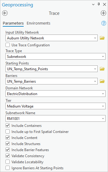
When running a subnetwork trace, defining a starting point is optional if you specify a Subnetwork Name value.
- Click Run.
On the map, all features that are connected in the subnetwork are selected. All the data from this tutorial is contained in the RM1001 subnetwork, so it was all selected.
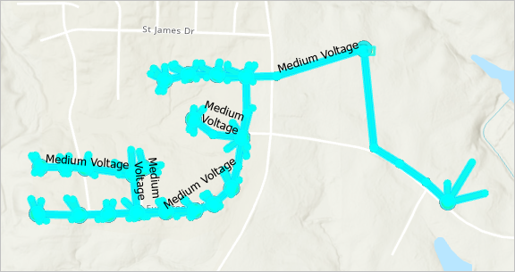
At the bottom of the map view, the Zoom to selected features button shows that 278 features are selected.

- Zoom to the transformer feature along Ogletree Rd.
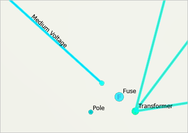
This time, the pole feature was selected by the trace.
- Clear the selection and close the Geoprocessing pane.
In this tutorial, you learned how to modify feature templates, create features, run traces, establish all three kinds of associations, modify terminal connections, and create and update subnetworks. You also explored the concepts of network topology, dirty areas, and subnetworks. With these fundamentals established, you have become more familiar with the utility network and the capabilities it provides for the accurate modeling of your network data.
You can find more tutorials in the tutorial gallery.

