Understand projections
You will not find a projection that is suitable for all maps. All projections distort the earth in some way. Each one seeks to preserve some geometric property at the expense of others.
Projection types
Conformal projections preserve angles locally, so the shapes of features appear true. But the cost of this quality is the distortion of areas and distances. Equal area projections preserve area, at the expense of angles, so the shapes of some places appear skewed. Equidistant projections preserve distances, although only from certain points or along certain lines on the map.
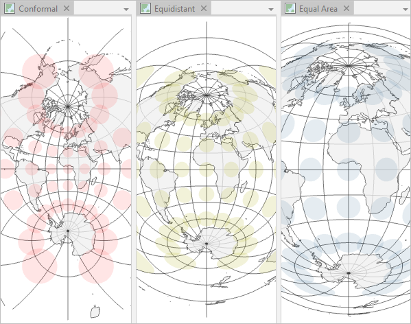
Compromise projections provide a representation of the earth that is not perfectly correct in any way but not badly distorted in any way either. They are usually used for maps of the entire world.
There are dozens of projections available in ArcGIS that can be configured into countless projected coordinate systems. Your choice of a projected coordinate system depends on many factors, including the part of the world you are mapping, the scale of your map, and the purpose of your map. You want to choose a projected coordinate system in which the places and properties that are most important to your map are the least distorted.
Map global analysis results
Map projections distort the grid of latitude and longitude lines, which means they also distort your data. You've taken great care to conduct an analysis of future precipitation changes properly and precisely. Next, you need to present your results on a map. You want to choose a projection that will allow you to present those results clearly, so they are not misinterpreted.
Find a global equal area projection
First, you'll explore a few traditional resources to help you find a suitable projection for your analysis results.
- Download the Map Projections project package.
- Locate the downloaded Map_Projections.ppkx file on your computer. Double-click the file to open it in ArcGIS Pro. If prompted, sign in using your licensed ArcGIS account.
Note:
If you don't have access to ArcGIS Pro or an ArcGIS organizational account, see options for software access.
The project has three maps. The Change in water storage map is active.
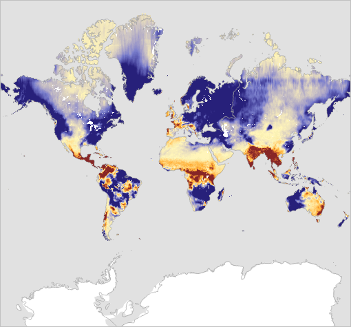
The data on this map shows change in water storage for every month since January 2000. The darkest blue areas had a 50 mm increase in storage, while the darkest brown areas had a 50 mm decrease. The map currently shows water storage for January 2000.
Note:
To view the data for every year, point to the time slider at the top of the map and click the Play button.
First, you'll find out which projection this map is using.
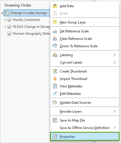
- In the Contents pane, right-click Change in water storage and choose Properties.
- In the Map Properties window, click the Coordinate Systems tab.
Under Current XY, the current coordinate system for this map is listed as WGS 1984 Web Mercator (auxiliary sphere).
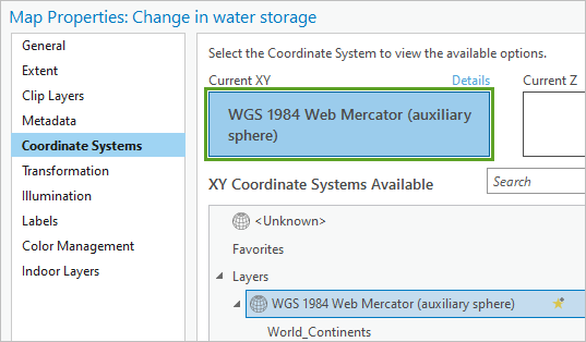
Web Mercator is a common projected coordinate system designed for web mapping applications. Most Esri basemaps are tiled in Web Mercator, so they can have the greatest compatibility. However, this projection does not preserve areas, distances, or angles.
Note:
You can click Details above the current coordinate system to display more information.
- In the Map Properties window, click Cancel.
Looking at this map, you may think that Greenland is many times larger than India. In fact, Greenland is slightly smaller than India. If the Web Mercator projection distorts the relative sizes of countries so dramatically, you know that it must also be distorting your analysis results.
This map suggests that only small areas saw a decrease in water storage, mostly near the equator. Web Mercator is not an appropriate choice for this map. Next, you'll consult a chart that compares projections to find one that is appropriate for your map.
- Open Quick Notes on Map Projections in ArcGIS.
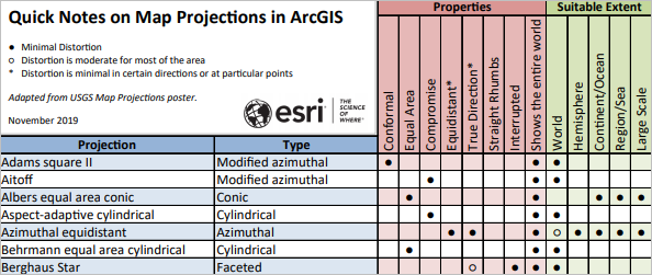
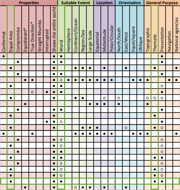
The property that is most important to preserve in your precipitation map is area. This is true for most maps presenting analysis results involving area, density, or distance comparisons.
- Use the chart to find a projection that meets the following criteria:
- Properties: Equal Area
- Suitable Extent: World
- General Purpose: Thematic
There are a few projections that are suitable for your map. One of them is Equal Earth.
- Go to the ArcGIS Pro help page for the Equal Earth projection. Scroll down and read the Usage section.
You can read about any projection found in ArcGIS to help you decide which is best for your map.
Change the map's projected coordinate system
You've decided to use the Equal Earth projection. Next, you'll apply it to your Change in water storage map.
- In ArcGIS Pro, in the Contents pane, double-click Change in water storage to open the Map Properties window.
- If necessary, click the Coordinate Systems tab.
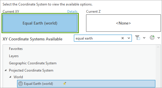
- In the search bar, type equal earth and press Enter.
The list of available coordinate systems filters based on your search.
- Expand Projected Coordinate System and expand World. Click Equal Earth (world).
The Current XY button updates to indicate that the map's coordinate system has changed.
Tip:
Changing the coordinate system in the Map Properties window affects only the map. It does not change the coordinate system of your data layers. The layers are projected on the fly to draw correctly on the map. To learn more about projection on the fly, read this blog article.
- In the Map Properties window, click OK.
The Equal Earth projected coordinate system is applied to your map.
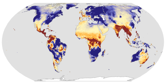
The analysis results are now presented in a form that preserves relative areas, so your map readers can accurately compare the areas of water storage changes.
- On the Quick Access Toolbar, click the Save Project button to save the project.
The following image compares the two projections at the same scale. How might the Web Mercator projection mislead or hinder people from properly interpreting your analysis results?
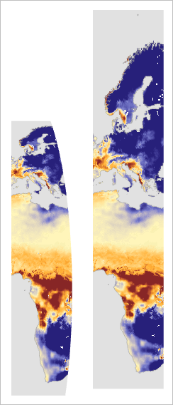
The Equal Earth projection is designed to show the entire world, but there are two parts of the world that it is unable to map effectively. Next, you'll try a projection designed to map polar regions.
Map polar data
A compass needle does not point to the true north pole. Instead, it points to the magnetic north pole, a location that is constantly changing. Next, you'll make a map to show the wandering path the magnetic pole has taken over the past 400 years. You also want to use this map to show whether the magnetic north pole is moving closer to, or farther away from, true north.
Find a polar equidistant projection
You'll search for a projected coordinate system that preserves distances from the north pole.
- At the top of the map view, click the North Pole tab to activate that map.

The view changes to show a different map.
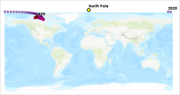
The data in this map was provided by NOAA National Centers for Environmental Information (NCEI).
The map does a poor job of illustrating the changing location of the magnetic north pole. The points all appear to be far away from the true north pole, and they are also split up on either side of the map. Measurements made on this map would be meaningless.
For this map's projection, you have two criteria:
- To display the arctic data more naturally, you need a projection designed for polar regions.
- To determine how close magnetic north is to true north, you need an equidistant projection, which will preserve accurate distance measurements to the north pole.
Next, you'll find an appropriate projected coordinate system by using a filter.
- In the Contents pane, double-click North Pole to open the Map Properties window.
Note:
This map currently uses a geographic coordinate system, WGS 1984. When a geographic coordinate system is selected, your map will be projected using the pseudo-plate carrée projection. You can read more about the difference between geographic and projected coordinate systems in this blog article.
- On the Coordinate Systems tab, click the Filter Coordinate Systems button.

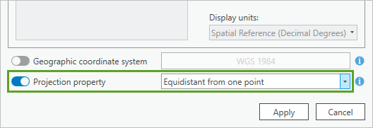
- At the bottom of the Filter Coordinate Systems window, turn on the Projection property toggle button. Click the drop-down menu and choose Equidistant from one point.
- Click Apply.
The list of available coordinate systems is filtered to only those that preserve distances when measured through the center of the projection.
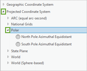
- Expand the Projected Coordinate System list and expand Polar.
Tip:
Drag the edges of the Map Properties window to make it larger.
There are only two projected coordinate systems, one for the north pole and one for the south pole.
- Click North Pole Azimuthal Equidistant and click OK.
This projection distorts both angles and areas. Distortion is extreme in the southern hemisphere.
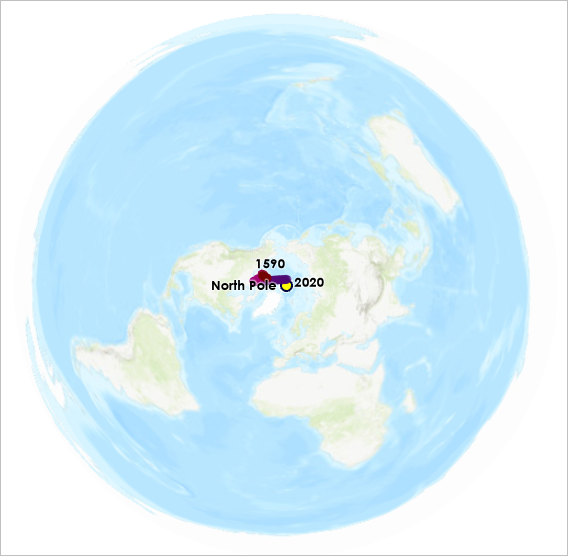
However, this projection is useful for mapping the area around the north pole. It preserves true distances and directions measured from the pole.
- In the Contents pane, right-click HistoricalMagneticPoleTrack and choose Zoom To Layer.
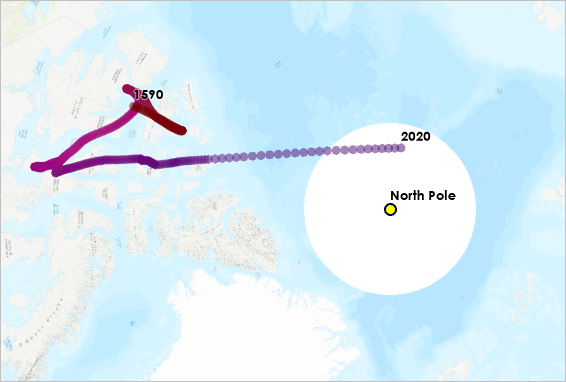
There are some problems with the Topographic basemap. This basemap was designed for the Web Mercator projection, so it becomes squished and stretched when it is reprojected onto the Azimuthal Equidistant map. Additionally, Web Mercator is unable to show the poles, so the basemap is cut off past 85° latitude, leaving a blank hole in your map.
The Topographic basemap is not suitable for your polar map, so you'll find one that is.
- In the Contents pane, right-click Topographic and choose Remove.
- In the Catalog pane, click the Portal tab and click the Living Atlas tab.
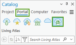
- In the search bar, type Polar Basemap and press Enter.
- From the search results, right-click Arctic Ocean Base and choose Add To Current Map.
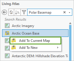
The map updates to display the new basemap, which covers the portion of the earth north of 50° latitude.
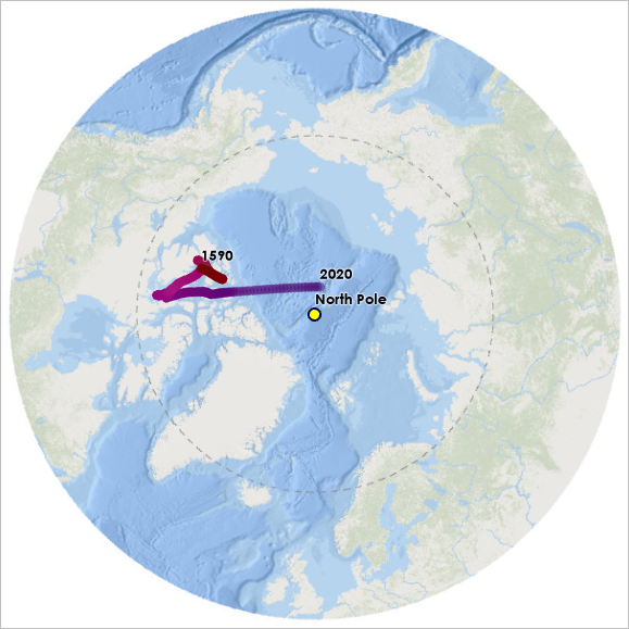
Find the northernmost magnetic pole
Next, you'll use your map to measure distances between true north and the wandering magnetic north pole, to determine the year when they were closest.
- On the toolbar below the map, make sure the Snapping button is highlighted.

Snapping will allow you to measure features more easily.
- On the ribbon, click the Map tab. In the Inquiry group, click the Measure button.

The Measure Distance window appears on top of the map.
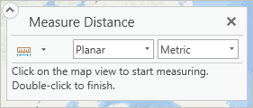
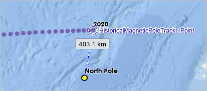
- Click the point labeled North Pole, and click the point labeled 2020.
Tip:
Hold the C key or the middle button of your mouse to pan on the map without deactivating the measure tool.The tool reports a distance of 403.1 kilometers (250.47 miles).
- On your keyboard, press Esc to clear the measurement.
- Measure the distance between the true north pole and some previous locations of the magnetic north pole.
Magnetic north was nearest to true north in 2018, when it was 394.16 kilometers (244.92 miles) away. It is now heading south, toward Russia.
You can make true distance measurements on this map because it uses an equidistant projection. However, no projection can preserve all distances. The azimuthal equidistant projection preserves distance and direction from the central point only. So measurements from the north pole are true, but measurements between any other locations on this map will be inaccurate.
Measure geodesic and planar distances
The measurements you've made so far have been planar. Planar distances are like measuring with a ruler on a paper map. Geodesic distances are like measuring with a string over the surface of a globe. Next, you'll compare planar and geodesic measurements between the magnetic north poles of 1590 and 2020.
- Press Esc to clear your current measurement.
- Measure between the point labeled 1590 and the point labeled 2020.
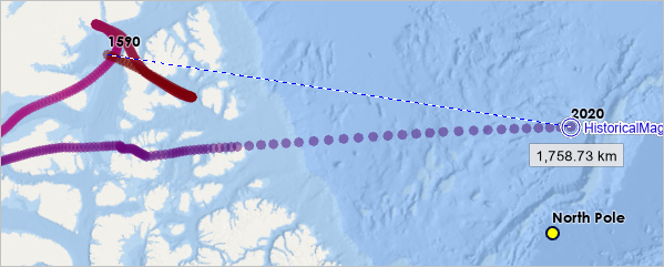
The distance reported between these two locations is 1,758.73 kilometers (1,092.82 miles). However, the only accurate planar distances that can be made on this map are from the center point. To find accurate distances between other locations, you need to make geodesic measurements.
- Press Esc. In the Measure Distance window, click the Planar menu and choose Geodesic.
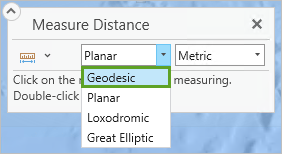
- Measure the distance between the poles of 1590 and 2020 again.
This time, the reported distance is 1,866.63 kilometers (1,159.87 miles). The geodesic distance is over 100 kilometers longer than the planar distance.
- Close the Measure Distance window.
Geodesic distances ignore the map's projection and provide a true distance. Planar distances are only true if the map uses a distance-preserving projection, and only to certain points or along certain lines.
The projected coordinate system you chose for this map was already centered on the north pole, which happened to be the location from which you wanted to measure. But what if you wanted to measure from a different point?
Modify a projected coordinate system
Next, you'll modify the existing coordinate system to center it on the 1590 magnetic north pole, so measurements can instead be made from that point.
- Zoom to the point labeled 1590 and click it.
The Longitude and Latitude are listed in the pop-up. The coordinates of the pointer can also be read in the toolbar beneath the map.
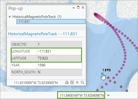
- Close the pop-up.
- On the Contents toolbar, double-click the North Pole map to open the Map Properties window. If necessary, click the Coordinate Systems tab.
- In the XY Coordinate Systems Available list, the current coordinate system should be highlighted.
Note:
If North Pole Azimuthal Equidistant is not highlighted, use the Search bar to find it.
- Right-click North Pole Azimuthal Equidistant and choose Copy and Modify.
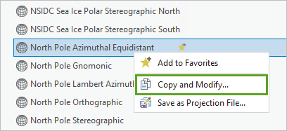
The Modify Projected Coordinate System window appears. Here, you can construct a custom coordinate system with parameters that match your needs.
- For Name, type 1590 Magnetic North Pole Equidistant.
The Projection is already set to Azimuthal Equidistant. A projection and a projected coordinate system are not the same thing. A projection is one parameter in a projected coordinate system. Other parameters include a geographic coordinate system, a linear unit, and a set of parameters that depend on the selected projection (central meridian, scale factor, and so on).
Note:
Learn more about coordinate systems in the blog article Coordinate Systems: What's the Difference?
You'll adjust the parameters for this projected coordinate system to center it on the chosen location, instead of true north.
- For Central Meridian, type -111.831. For Latitude Of Origin, type 73.923.
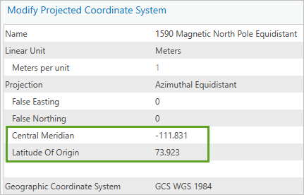
These are the values you observed in the pop-up.
- Click Save.
1590 Magnetic North Pole Equidistant is now set as the Current XY coordinate system for your map. It is also listed in the Custom category of available coordinate systems.
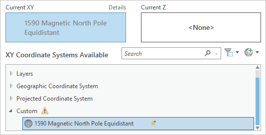
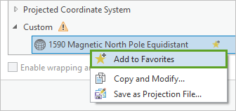
Coordinate systems in the Custom category are not saved. Next, you'll add it to a favorites folder so you can use it in future maps.
- Under Custom, right-click 1590 Magnetic North Pole Equidistant and choose Add to Favorites.
- Scroll to the top of the coordinate systems list and expand the Favorites group to ensure that 1590 Magnetic North Pole Equidistant is listed there.
Note:
Favorite coordinate systems are stored as .prj files in C:\Users\<your user name>\AppData\Local\ESRI\ArcGISPro\Favorites.
- In the Map Properties window, click OK to commit the change.
The map redraws with the new projected coordinate system. It looks similar to before, but the center of the map (if not the basemap) has shifted. Both geodesic and planar measurements from the new point will now be accurate.
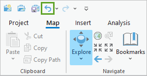
- On the Quick Access Toolbar, click the Undo button to return the map to the projected coordinate system that is centered on true north.
- Save the project.
In ArcGIS, you can choose between planar or geodesic measurements. But your map reader will not have this choice; they will only see a flat map on a screen or piece of paper. An equidistant projection is the right choice for this map to allow everyone to assess distance correctly from the north pole.
Sometimes, you won't find a projected coordinate system that is ready-made for your map's purpose. ArcGIS Pro allows you to modify any coordinate system to have parameters that better suit your needs. Next, you'll learn how to create a custom projected coordinate system using suggested parameters from ArcGIS Pro.
Map the border of two UTM zones
Universal Transverse Mercator (UTM) is a system that is commonly used for large-scale maps. If your map is narrower than 6° of longitude, you can map it with a UTM projected coordinate system. The map you'll make next is narrow enough but doesn't fit properly into an existing UTM zone. You'll learn how to find the correct UTM projected coordinate system for an area of interest, and how to create a custom projected coordinate system to use when a standard UTM zone doesn't fit.
Find the correct UTM zone
You want to map the border between Finland and Russia. This will be a reference map, meant to give descriptive context to the border region. You want to use a conformal projection to show the shapes of features in their most recognizable forms.
- At the top of the map view, click the Border tab to activate the map.
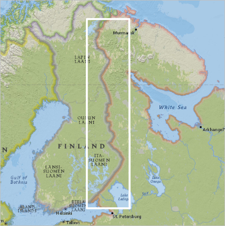
This map currently uses the Web Mercator projection. While the Mercator projection is conformal, Web Mercator (Mercator Auxiliary Sphere) is not. In addition, this projection distorts area and distances dramatically in higher latitudes.
The white rectangle represents the area you want to map. Because this is a narrow piece of the earth—within 6° of longitude—you can use a UTM zone. UTM projected coordinate systems are conformal and their distortion of other map properties is minimal.
UTM divides the earth into 60 zones. You'll use a spatial filter to determine which UTM zone to use for your map.
- In the Contents pane, double-click Border to open the Map Properties window.
- On the Coordinate Systems tab, next to the search bar, click the Filter Coordinate Systems button.

- In the Filter Coordinate Systems window, turn on Spatial extent.

- In the Filter Coordinate Systems window, click Map Neatline.
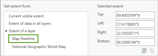
The values under Selected extent update to match the extent of the Map Neatline layer.
- Click Apply.
The XY Coordinate Systems Available list is filtered to only contain coordinate systems with extents that overlap with your map.
- In the list, expand Projected Coordinate System, UTM, WGS 1984, and Northern Hemisphere.
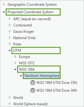
There are two UTM zones for the area that you want to map, 35N and 36N, and you can't tell from this list which zone is best.
- Click Cancel to close the Map Properties window.
Next, you'll add a layer to your map to visualize the UTM grid.
- If necessary, in the Catalog pane, click the Portal tab and click Living Atlas.
- In the search bar, type UTM Grid and press Enter.
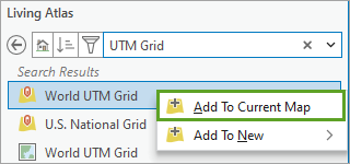
- In the search results, right-click World UTM Grid and choose Add To Current Map.
Next, you'll label the UTM zones by their zone number.
- In the Contents pane, right-click World_UTM_Grid and choose Label.
The UTM grid is not labeled with the correct field. You can change the label field from the Labeling tab.
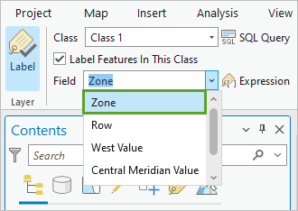
- On the ribbon, click the Labeling tab. In the Label Class section, for Field, click the drop-down menu and choose Zone.
The Finland-Russia border lies on the border of two UTM zones: 35 and 36.
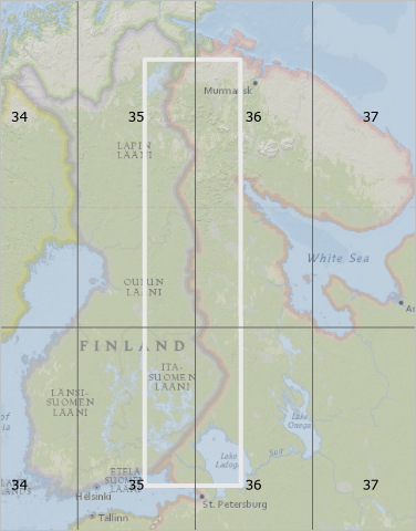
UTM projected coordinate systems minimize distortion to reasonable levels, but only within their zone areas. Neither zone 35 nor 36 will provide this benefit for your map area.
- In the Contents pane, right-click World_UTM_Grid and choose Remove.
The World_UTM_Grid layer confirmed that the best choice for this map is a custom projected coordinate system. Next, you'll create one for this region.
Create a custom projected coordinate system
ArcGIS Pro can suggest new custom projected coordinate systems based on two criteria: distortion property and map extent.
- In the Contents pane, double-click Border to open the Map Properties window.
- On the Coordinate Systems tab, click the Add Coordinate System button and choose New suggested projected coordinate system.
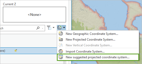
A new window appears.
- For Coordinate System Name, type Finland-Russia Border. Leave Geographic coordinate system set to WGS 1984.

- Under Get extent from, click Map Neatline.
The values under Selected extent update to match the extent of the Map Neatline layer.
- For Projection property, choose Conformal.
The parameters of the new custom projected coordinate system appear in the Result box.
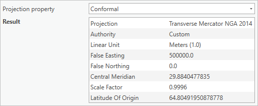
The Projection is set to Transverse Mercator NGA 2014. This is a variant of the Transverse Mercator projection used by UTM zone maps.
Note:
Transverse Mercator is a common projection, used by the UTM coordinate systems and some State Plate coordinate systems. Transverse Mercator NGA 2014 is a variant of this projection, with the added advantage of being able to show a larger portion of the world.
The Central Meridian and Latitude Of Origin parameters are taken from the center of the Map Neatline rectangle.
The False Easting shifts the origin point of the coordinate system far away from your map area to ensure that no coordinates have negative values. The Scale Factor minimizes distortion across the entire 6° zone.
- Click Save.
- In the Map Properties window, under Custom, right-click Finland-Russia Border and choose Add to Favorites.
- Click OK to commit the change.
The map redraws with the new projected coordinate system.
- In the Contents pane, right-click National Geographic World Map and choose Zoom To Layer.
The new projected coordinate system distorts shapes that are far from its central meridian (29.9° E).
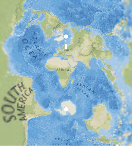
Even though this map can show the entire world, it is only appropriate to map areas in the middle of this coordinate system—within 3° of its central meridian.
- Zoom to the Map Neatline layer.
The following image shows a comparison of the map in the new custom projected coordinate system and in Web Mercator:
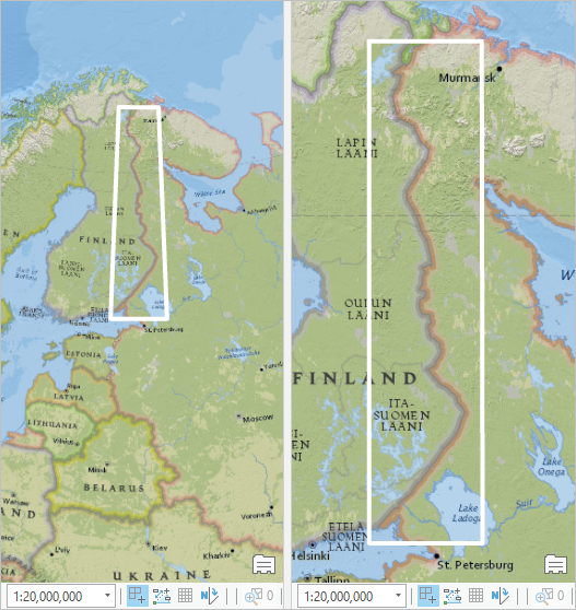
In the custom coordinate system, the shape of the neatline polygon is a trapezoid instead of a rectangle. Its northern edge is shorter than its southern edge. The rectangle in Web Mercator is misleading: on the earth, these lines are not the same length. The new projection represents them more accurately.
The two maps shown above are drawn at the same scale: 1 to 20 million. But that scale is meaningless in the Web Mercator map, since its area distortions are so extreme. Distortion in the Transverse Mercator map is small enough to be unnoticeable, and more precise measurements can be made on that map.
- Save the project.
Earlier in this tutorial, you learned how to modify coordinate systems. How could you modify an existing UTM coordinate system to center it on the Russia-Finland border? How could you modify the Equal Earth projection from the start of this tutorial to better show the Pacific Ocean?
Tip:
Copy and modify any WGS 1984 UTM Zone coordinate system. Change the central meridian to 29.9.
Copy and modify the Equal Earth (world) coordinate system. Change the central meridian to 160°W or a similar value.
In this tutorial, you learned some techniques and explored resources that will help you choose an appropriate map projection:
- Consult the Quick Notes on Map Projections in ArcGIS chart.
- Review the ArcGIS help documentation for supported map projections.
- Filter coordinate systems based on projection properties and spatial extents in ArcGIS Pro.
- Copy and modify existing projected coordinate systems in ArcGIS Pro.
- Access the UTM Grid reference layer in ArcGIS Living Atlas of the World.
- Create a custom projected coordinate system in ArcGIS Pro with an extent and projection property.
Take a closer look at the maps you see on the internet, in the news, or in apps. Do they use a projection that is well suited to their purpose? Are their distance and area measurements accurate?
The consequences of ignoring your choice of map projection include distorting your data and misleading your map readers. However, if you spend some time to find an appropriate projected coordinate system, you'll create a map that presents your data and your message clearly and accurately.
You can find more cartography tutorials on the Introduction to Cartography page.
You can find more tutorials in the tutorial gallery.
